Hey everyone
I have been doing some testing on the thermal performance of an odrive V3.5 48V board. I expect results will be similar for all versions with the black heatsinks. The versions with the gold heatsinks may be slightly worse due to their lower quality thermal pads.
tldr:
Tests of the onboard thermistors show that they underestimate the MOSFETs temperature by 15C when operating at high currents and temperatures and so a safety margin of 25C is suggested. The measurements shown below indicate you should not exceed the following current set-points if you intend to operate your odrive at 100% load indefinitely (ebike, direct drive robot arm etc.) or else you risk overheating:
Heatsink only in still air: 40A
Heatsink with basic fan cooling: 75A
Heatsink with overkill fan cooling: 90A
Warning: You will overheat most motors before reaching the limits shown above so be sure to always keep an eye on your motor temperature!
Method
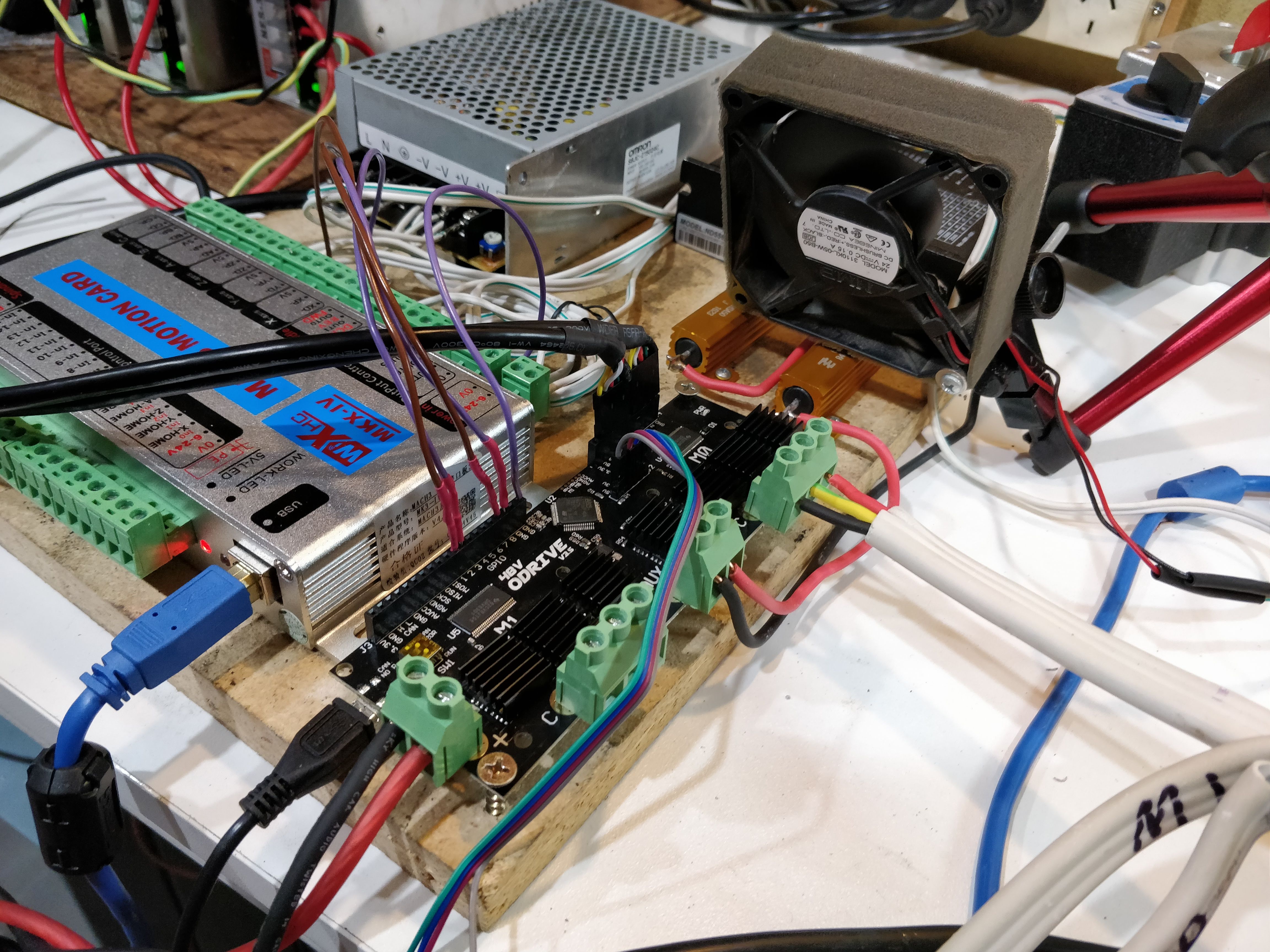
Odrive V3.5 48V with stock included heatsinks. Powered by 3 x 48V, 7.3A MeanWell switch mode power supplies. I am using two 150kV D6374 wired in parallel on M0 (both motors on a single channel) to act as a load for the odrive. Note that the motors can not be used this way for any practical purpose and they were only wired in parallel to help dissipate the heat generated by testing. The current was limited in firmware and the load provided by setting the motors to do an index search so that all MOSFETs experience a roughly equal load. No testing on the break resistor MOSFETs was undertaken. Ambient temperature of 13.2C for all tests. The onboard thermistor temperature was logged by modifying the ‘liveplotter’ function in the odrivetool to output the values to a text file. You can find a copy of the modified odrivetool here. To use it just replace your own copy of odrivetool and run ‘odrivetool liveplotter’ from a fresh Anaconda prompt window if you want to replicate these results.
Results
1. Temperature offset
All odrive boards have integrated thermistors located next to the MOSFET packages.
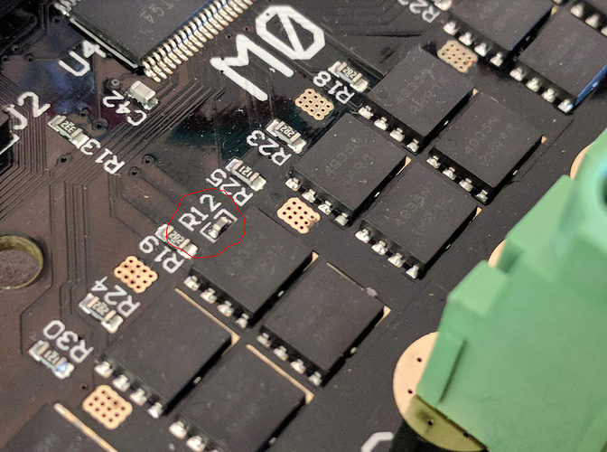
As of the latest firmware release the temperature of these thermistors can now be read using odrivetool. See this thread for more details. Before using the temperature readings of the thermistors @madcowswe suggested that it would be a good idea to first check that their readings are accurate. This was done by comparing the thermistor temperature reading to that of a thermocouple taped to the top of a bare MOSFET package.

During previous measurements I have soldered the thermocouple directly to the pad under the MOSFETs but I have since found that doing so leads to a large underestimation of the package temperature due to the time it takes for the heat to travel to the underside of the board.
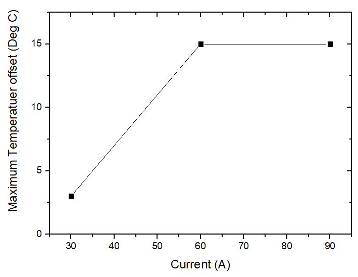
A maximum temperature differential of 15C was observed between the MOSFETs and the thermocouple when operating at high currents and temperatures. Therefore I would suggest a 25C safety margin when relying on the thermistor temperature. With this in mind, I will keep the temperature reported by the board below 100C for the following tests.
2. Temperature rise under different cooling conditions and currents
Test 1: Exposed board in open air
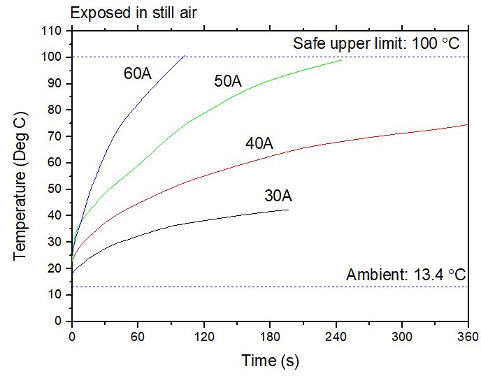
If you plan on running your odrive at 100% load without a fan in a big enclosure or in open air then I would recommend keeping your current below 40A.
Test 2: Exposed board in open air with a realistically sized fan
This test uses a quiet 80mm PC fan to blow air gently over the heatsinks.
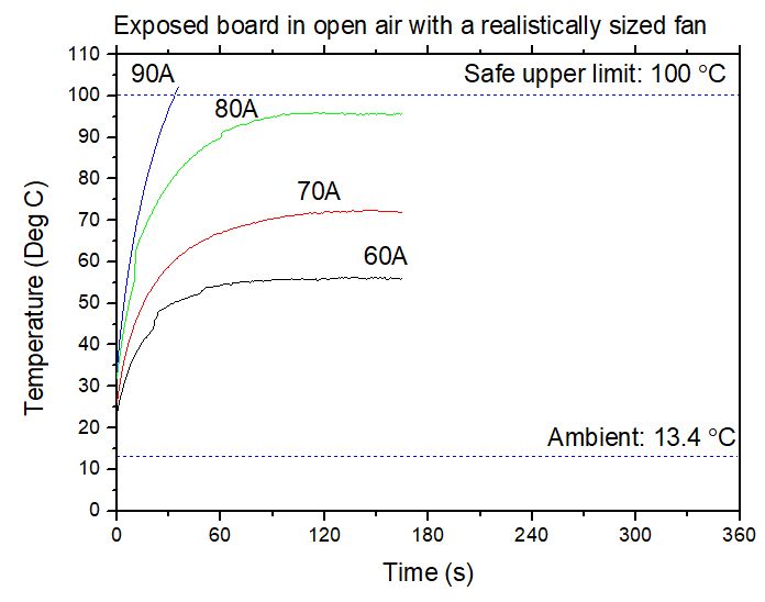
With the addition of this PC fan a constant current of 70 to 80A is achievable.
Test 3: Exposed board in open air with overkill fan
In this setup I used a powerful blower fan placed directly over the M0 MOSFETs. This setup is noisy and impractical but it shows the upper limits of what can be achieved with air cooling and the stock heatsinks. Note that I place a layer of tape over the thermistor so that it is not also cooled by the powerful fan and instead hopefully still reflects the board temperature.

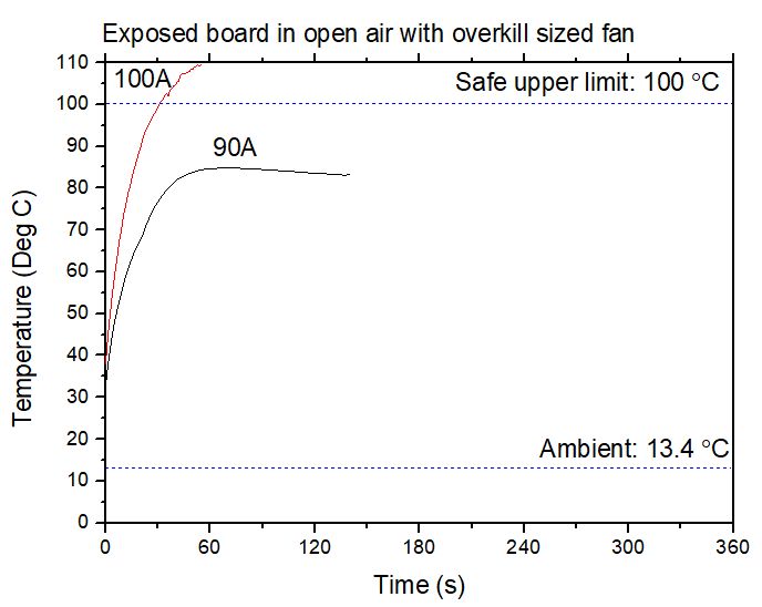
Here we see 90A is achievable, but its really not worth the added noise and bulk of the blower fan. It is likely that a bigger heatsink mounted with proper thermal compound could yield similar results with the quieter PC fan.
If you plan on using this data for your own work make sure to consider the maximum ambient temperature your board will be exposed to and how that will impact your temperatures. For example, if you place your board in a water tight enclosure, put it on an ebike and take it for a ride on a warm 35C day then you may need to halve the current values listed above to prevent overheating.
