ODrive Pro (firmware 0.6.11)
Arc Motion motor (15 pole-pairs )
AksIM-2 off-axis magnetic encoder, 17 bit BiSS-C
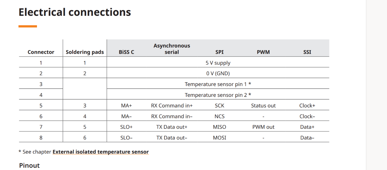
Wiring (per datasheet):
MA+ → G0+ (clock+)
MA– → G0– (clock–)
SLO+ → G18+ (data+)
SLO– → G18– (data–)
- MOSI left unconnected (BiSS-C is read-only)
Code:
odrv.spi_encoder0.config.mode          = SpiEncoderMode.BISSC
odrv.spi_encoder0.config.ncs_gpio      = 17
odrv.spi_encoder0.config.biss_c_bits   = 17
axis.config.commutation_encoder        = EncoderId.SPI_ENCODER0
axis.config.load_encoder               = EncoderId.SPI_ENCODER0
axis.config.encoder_bandwidth          = 90
What I observe:
- In “Quick Setup” there is no BiSS-C option.
- After setting the above in Attributes, I click “Save & Reboot.”
- When I attempt MOTOR_CALIBRATION or ENCODER_OFFSET_CALIBRATION, the GUI shows no_response or not_calibrated.
Question:
What am I missing in my BiSS-C wiring or ODrive configuration? Why does the ODrive Pro not see any BiSS-C data?
Thanks for the info! Would you mind showing an actual picture of your wiring, between the ODrive and the encoder?
Additionally, can you check the status of odrv.spi_encoder0.warning?
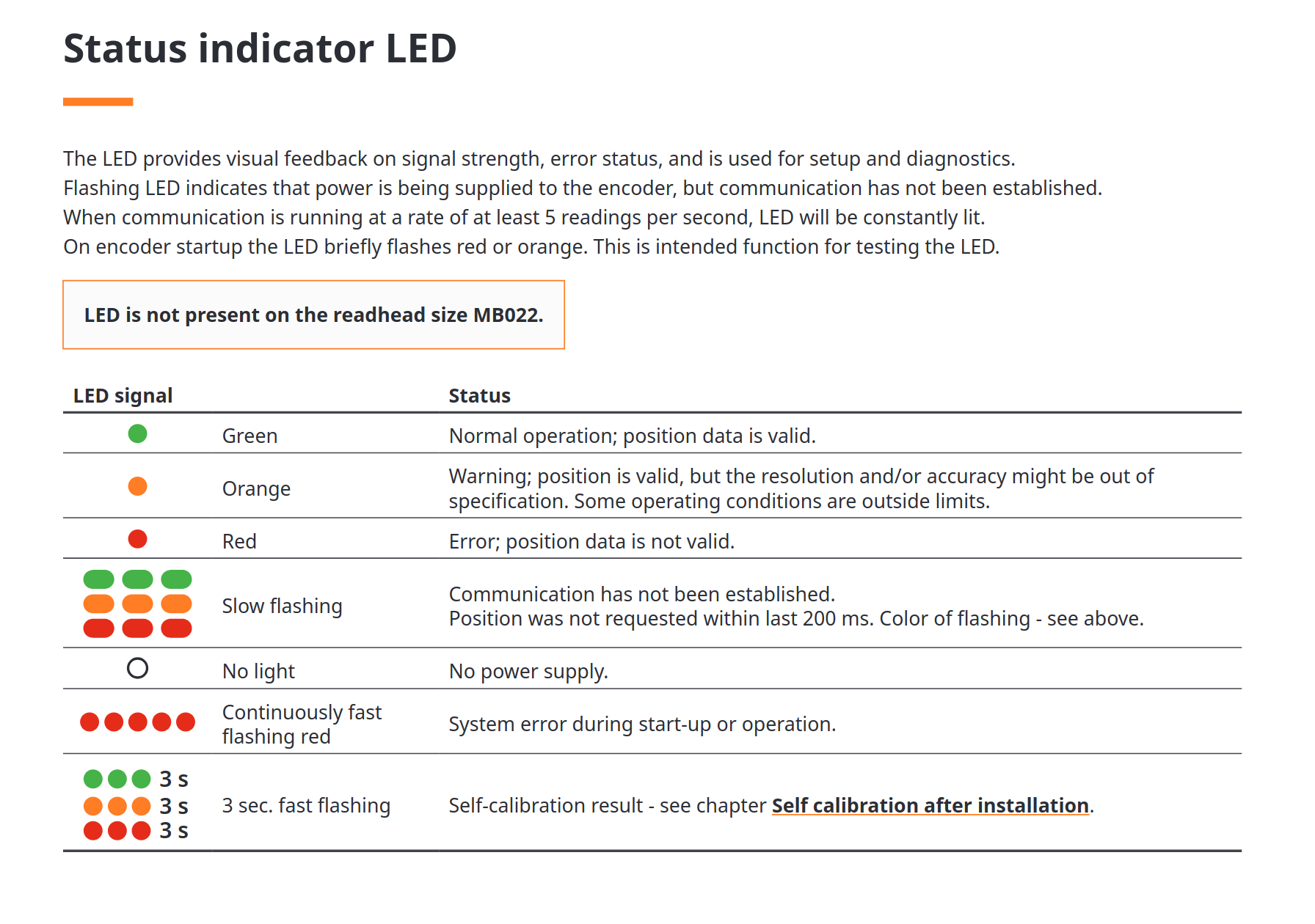
Note the AksIM-2 is very sensitive to mounting and installation error, I would check to make sure the status LED on the AksIM-2 is green, and not orange or red:
1. Hardware & Wiring
- Encoder: AksIM-2, 17 bit, true-absolute magnetic
- ODrive Pro pins (single-ended SPI):
- SCK → G0+ (leave G0– floating)
- nCS → G17+ (leave G17– floating)
- MISO → G18+ (leave G18– floating)
- MOSI → G14 (tied low when unused)
- 5 V → 5 V+; GND → GND
- Differential “–” pins: all left unconnected for single-ended mode
- Grounding: encoder GND, ODrive GND (and any adapter GND) common
2. GUI / Attribute Settings
python
CopyEdit
# Axis encoder assignment
odrv.axis0.config.load_encoder         = EncoderId.SPI_ENCODER0
odrv.axis0.config.commutation_encoder  = EncoderId.SPI_ENCODER0

# SPI-encoder settings
odrv.spi_encoder0.config.mode        = SpiEncoderMode.RLS
odrv.spi_encoder0.config.ncs_gpio    = 17
- I click Save & Reboot, then issue MOTOR_CALIBRATION and ENCODER_OFFSET_CALIBRATION.
- Calibration shows No_RESPONSE or not_calibrated
4. Already-checked Items
- Physical continuity on G0+, G14, G17+, G18+ — no shorts, solid solder joints.
- Power rails: encoder sees 5 V, LED on encoder lights steady when clock pulses present.
- Pin-mode: Verified in Attributes that G0/G14/G17/G18 are in SPI mode (not left in default GPIO).
- Floating “–” pins: Confirmed G0–, G17–, G18– are not tied to ground or any other signal.
Hi - sorry, you first posted BiSS-C setup and wiring, and now SPI? Are you using a BiSS-C or SPI readhead? Can you send some pictures? What’s the actual part number of your readhead?
1. Hardware Details:
- Motor: Kollmorgen TBM2G-11513 (Model A)
- Encoder: AksIM-2 (RLS), 17-bit, true-absolute, BiSS-C protocol
- Motor Connector: MB053DCC17BENT00 (Redhead)
- Controller: ODrive Pro (Firmware 0.6.11)
- Encoder Wiring (Differential BiSS-C attempt):
- MA+ → G0+ (Clock+)
- MA– → G0– (Clock–)
- SLO+ → G18+ (Data+)
- SLO– → G18– (Data–)
- MOSI left unconnected (BiSS-C is read-only)
2. Observations When Using High Current Motor Type:
When we select the High Current Motor type in the GUI, the motor fails to calibrate and frequently throws Unbalanced_Phases errors, even though the motor and wiring have been verified for continuity and correct phase connections.
3. Observations with BiSS-C Encoder:
We initially configured the encoder in BiSS-C mode, using:
odrv.spi_encoder0.config.mode = SpiEncoderMode.BISSC
odrv.spi_encoder0.config.ncs_gpio = 17
odrv.spi_encoder0.config.biss_c_bits = 17
axis.config.commutation_encoder = EncoderId.SPI_ENCODER0
axis.config.load_encoder = EncoderId.SPI_ENCODER0
Despite saving and rebooting, MOTOR_CALIBRATION or ENCODER_OFFSET_CALIBRATION fail with either no_response or not_calibrated. There is no BiSS-C option available in the GUI’s encoder dropdown either.
We observed:
- The LED on the AksIM-2 lights green, indicating clock signal presence.
- We verified G0/G14/G17/G18 pin modes are set to SPI and not GPIO.
- Physical wiring was confirmed to be solid with no shorts.
4. Single-Ended SPI Configuration Attempt:
Due to lack of response in BiSS-C mode, we also attempted configuring the encoder as single-ended SPI based on a forum suggestion. For that, we rewired as follows:
- SCK → G0+
- nCS → G17+
- MISO → G18+
- MOSI → G14 (tied low)
- All differential “–” pins left floating
- Common ground between encoder and ODrive
And used:
odrv.spi_encoder0.config.mode = SpiEncoderMode.RLS
odrv.spi_encoder0.config.ncs_gpio = 17
However, even with this change, ODrive fails to receive data. Motor/encoder status reports no_response or not_calibrated, and we are unsure if the AksIM-2 is even supported in SPI single-ended mode.
Our Key Questions:
- What is the correct mode to use with the AksIM-2 (BiSS-C encoder)? Is single-ended SPI a valid fallback or not supported at all?
- Could the phase imbalance errors be related to encoder feedback or a deeper motor compatibility issue with ODrive?
- Are there any known limitations or compatibility issues with the TBM2G series motors or AksIM-2 encoders on ODrive Pro v0.6.11?
- Can you provide guidance on how to confirm whether BiSS-C data is being received correctly at the hardware/firmware level?
Hi,
- What is the correct mode to use with the AksIM-2 (BiSS-C encoder)? Is single-ended SPI a valid fallback or not supported at all?
Not supported at all, it’s a distinctly different protocol than BiSS-C, and the encoder will not support it.
- Could the phase imbalance errors be related to encoder feedback or a deeper motor compatibility issue with ODrive?
This is almost always a wiring or configuration issue.
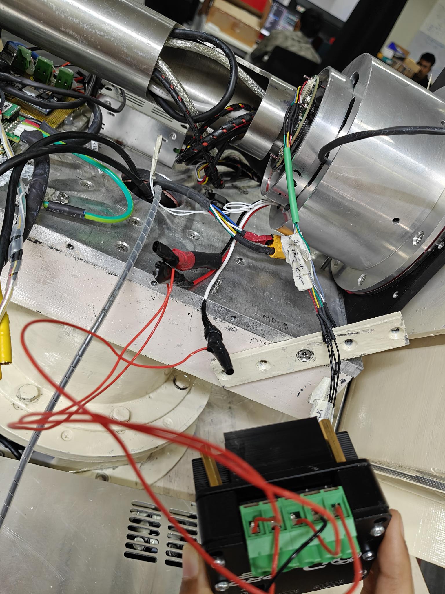
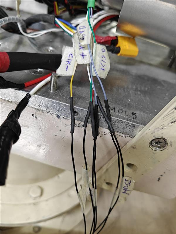
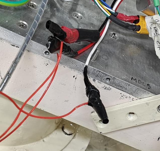
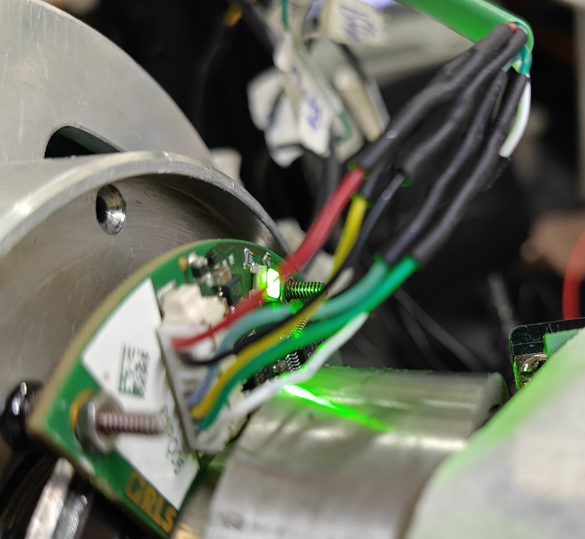
Your wiring here looks really sketchy. Can you confirm that these connections are adequetely soldered?
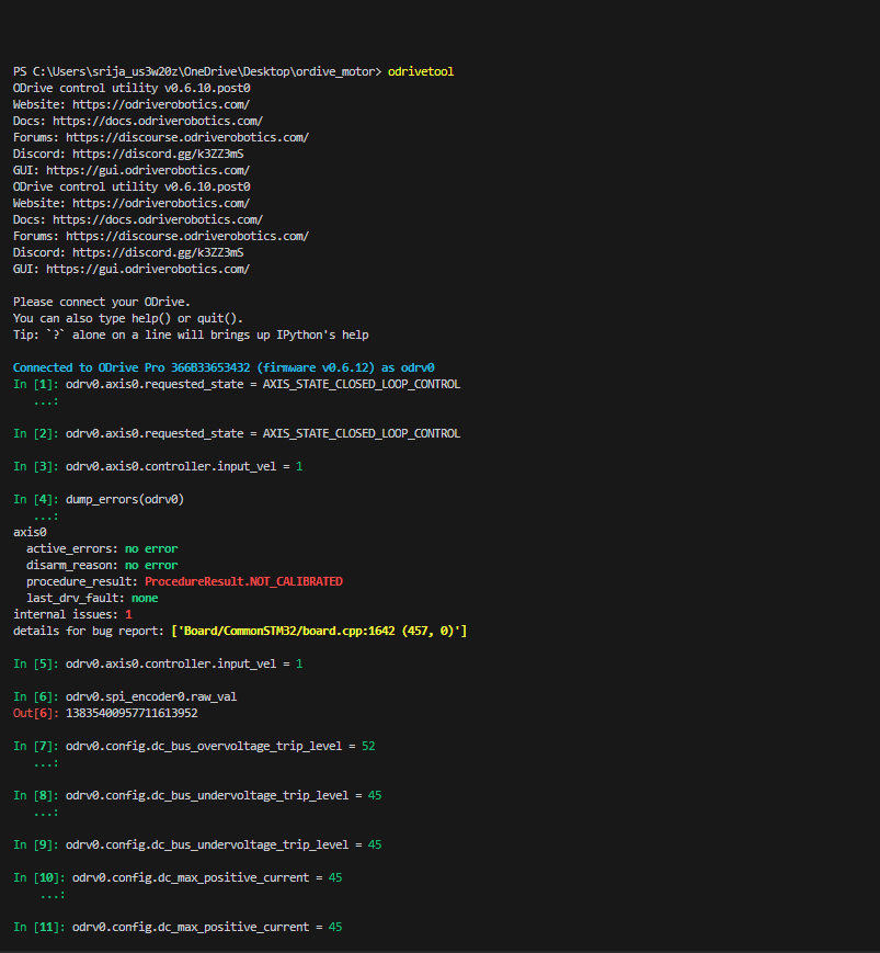
To help more, I also need your values of:
axis0.config.motor.resistance_calib_max_voltage
axis0.config.motor.calibration_current
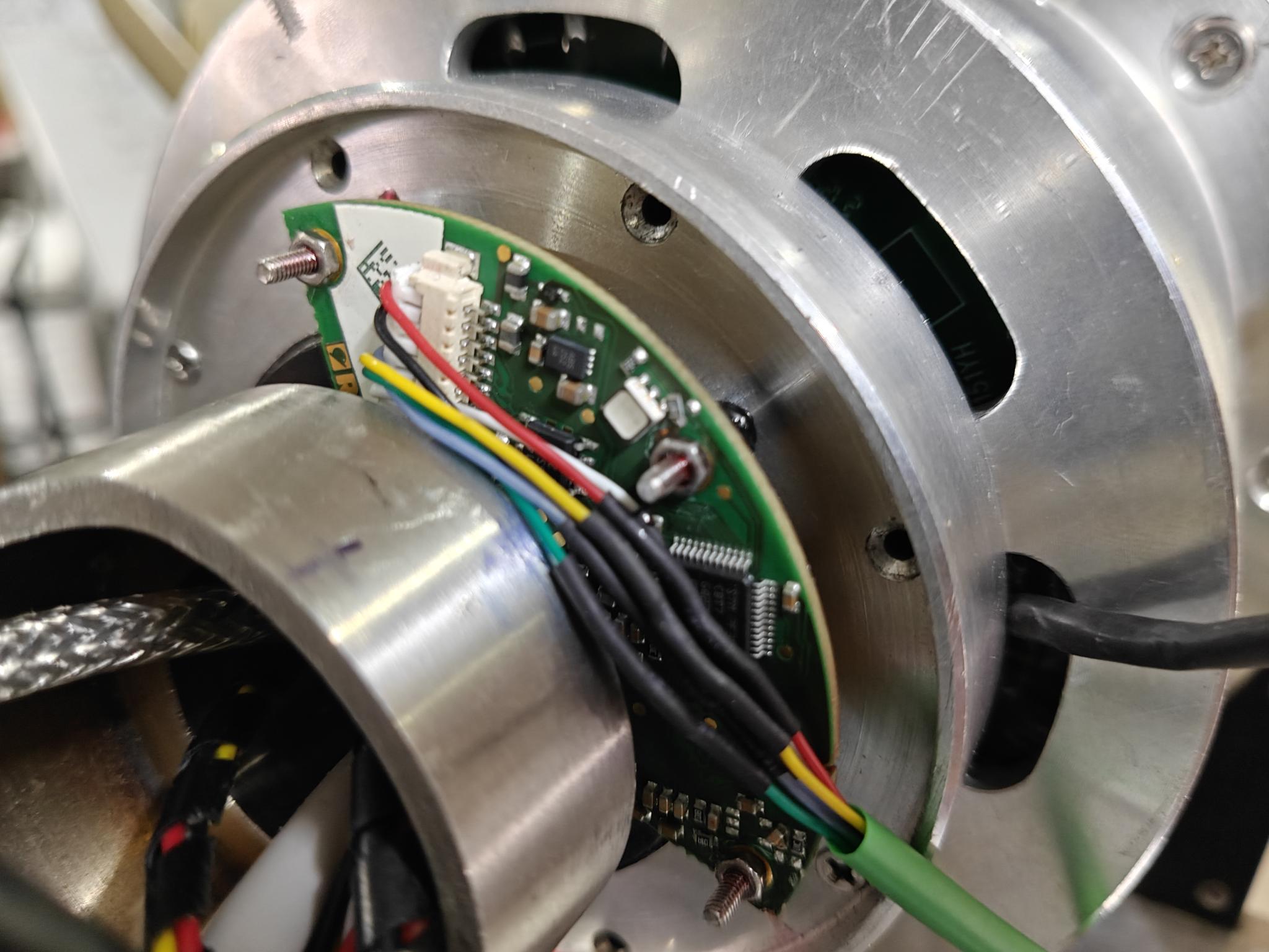
I also worry about your connection of the encoder, are these connections all soldered?
- Are there any known limitations or compatibility issues with the TBM2G series motors or AksIM-2 encoders on ODrive Pro v0.6.11?
No, this should work fine. BiSS-C is experimental, but we know it works with 18-bit AksIM-2, it should be fine with 17-bit too.
Can you provide guidance on how to confirm whether BiSS-C data is being received correctly at the hardware/firmware level?
You will need an oscilloscope or logic analyzer. Do you have either of these?
Thanks! I solved the imbalance phases errors by changing the U,V,W phase wires.
But, I am still stuck at NO_RESPONSE error. For this, what connection should I follow then, for my encoder. I am still unclear about it. I am attaching the 8-pin connector configuration of my encoder. Please check that out once, and let me know.
Once, guide me through the connections and consequent modes to select from the GUI.
Hi - your wiring was correct in your first post. I’ve asked for additional information, can you please provide this?
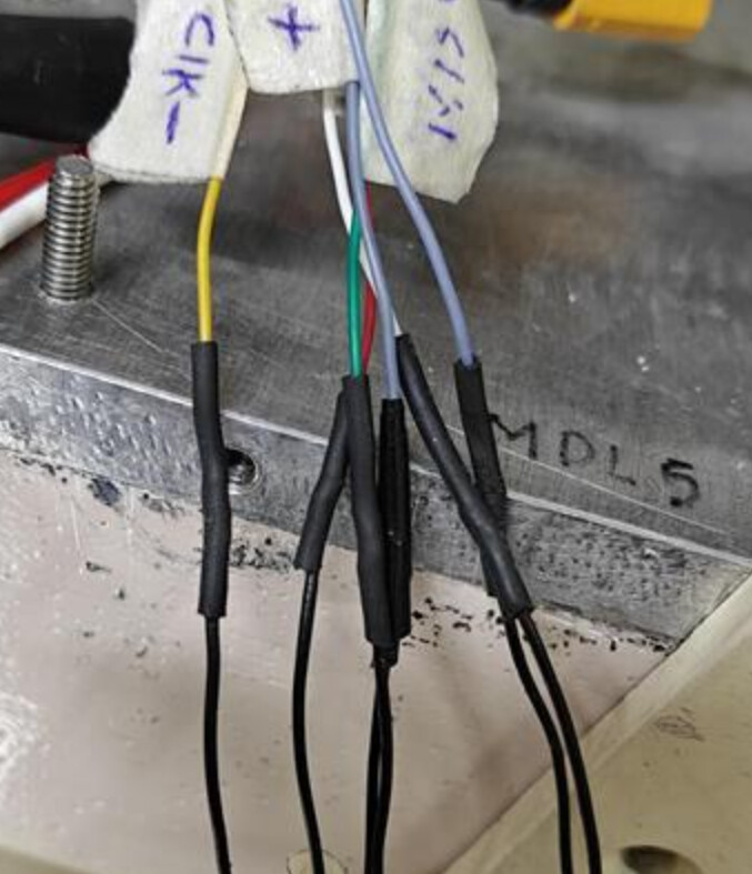
- Would you mind showing an actual picture of your wiring, between the ODrive and the encoder?
- Additionally, can you check the status of
odrv.spi_encoder0.warning?
- Please set G0/G14/G17/G18 modes to AUTO.
I have already set gpio_mode to AUTO for GPIO 0/14/17/18.
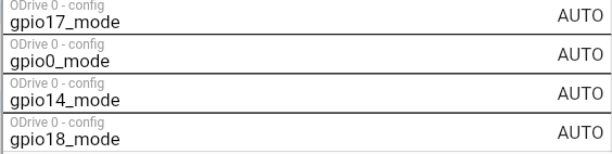
This has given me no improvement.
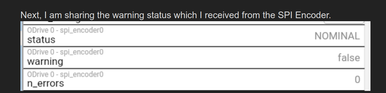
Next, I am sharing the warning status which I received from the SPI Encoder.
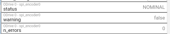
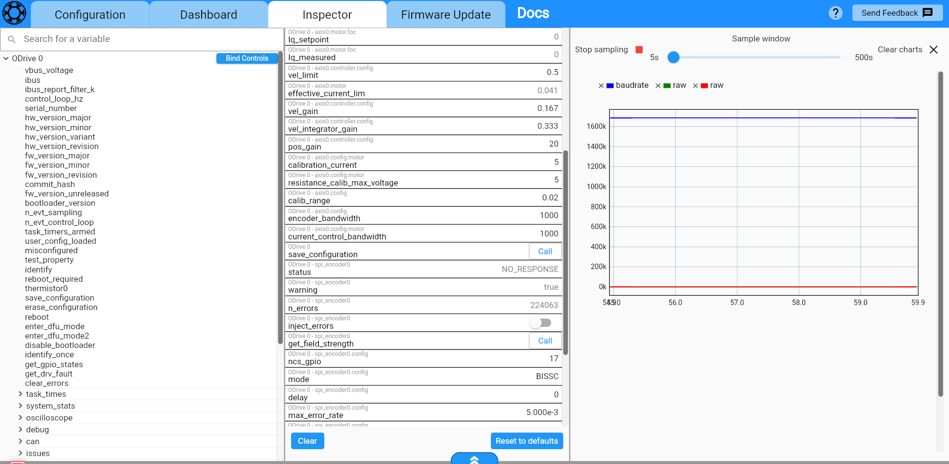
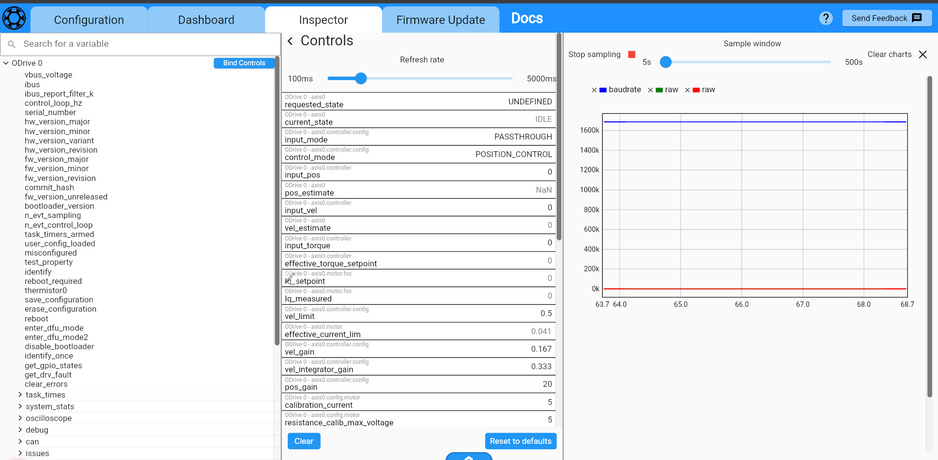
After some hit and trials, I noticed one thing. when I am selecting SPI_ENCODERMODE as RLS, I am getting some constant value of 0.25 in pos_estimate. For this, n_errors remain 0. And when I am selecting BISS_C, I am getting NaN in pos_estimate. For this, n_errors remain increasing continuously.
Now, I am still stuck in getting continuous position. Can you please once check this situation out. If there is any means of conference call and resolving this issue immediately, that would also be very helpful.
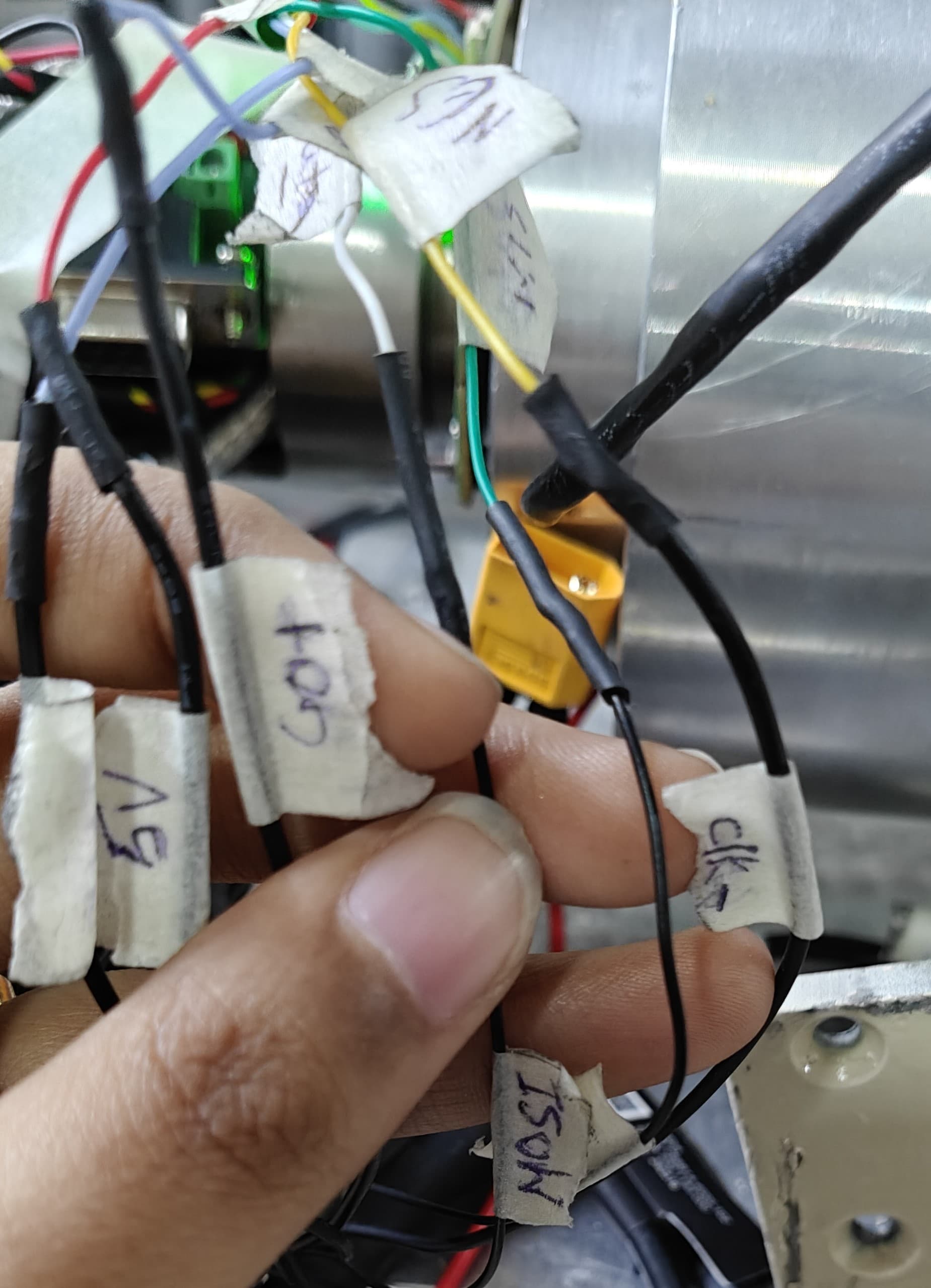
I am attaching the wiring photo also.
Don’t use SPI Encoder mode RLS, that’s for the RLS Orbis encoder.
Is this with encoder mode as BiSS-C or as RLS? If it’s as encoder mode RLS, please share with it as BiSS-C. Note you must run save_configuration after changing the encoder mode.
I understand. I got this via RLS. I am sending the one which I got via BISS_C.
Here, I am getting pos_estimate as NaN.
n_errors is increasing, warning is true, and status is NO_RESPONSE. I have done Save_Configuration.
Then, what should be done in this situation?
Here is some firmware with additional debug info: ODrivePro_BissCDebug.elf - Google Drive
You can install it with odrivetool new-dfu ODrivePro_BissCDebug.elf.
You will have to use ODrivetool for the testing, as the GUI will not recognize the debug parameter.
Please run the following for setup:
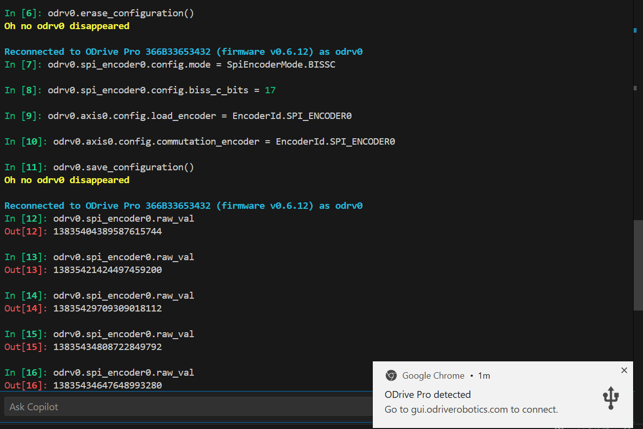
odrv0.erase_configuration()
odrv0.spi_encoder0.config.mode = SpiEncoderMode.BISSC
odrv0.spi_encoder0.config.biss_c_bits = 17
odrv0.axis0.config.load_encoder = EncoderId.SPI_ENCODER0
odrv0.axis0.config.commutation_encoder = EncoderId.SPI_ENCODER0
odrv0.save_configuration()
Then, send me the value of odrv0.spi_encoder0.raw_val at a few different approximate angles – you can just read the value while moving the encoder to a few positions by hand, it doesn’t need to be precise. Let me know that value, and I can look into the data to see what the issue is here. Once you send me this information, I should be able to diagnose and/or fix the issue very quickly.
Okay, so I did the following steps and this is what I did:
I am getting some values… but the change of values even on moving long distances remains like this. I have manually rotated it for around 270 degrees and stopped in different places and got this value… what is happening?
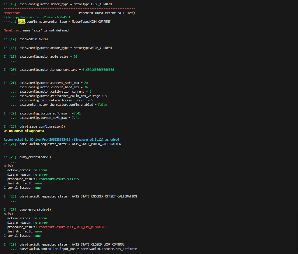
And since I got some values, I started doing the calibration process again and got pole_pair_cpr_mismatch.
I am getting some values… but the change of values even on moving long distances remains like this. I have manually rotated it for around 270 degrees and stopped in different places and got this value… what is happening?
The raw_val is the raw data from the encoder, before parsing and processing. BiSS-C is a complicated protocol, so the raw data frame doesn’t represent the actual encoder angle.
That being said, POLE_PAIR_CPR_MISMATCH implies that the encoder data is at least being received, which is different from previous where you’d get NO_RESPONSE.
This implies to me that you previously had your encoder configured incorrectly.
Can you please show the output of odrv0.spi_encoder0 at a few different positions?
Once we verify that you’re now getting correct data, we can debug the POLE_PAIR_CPR_MISMATCH issue.