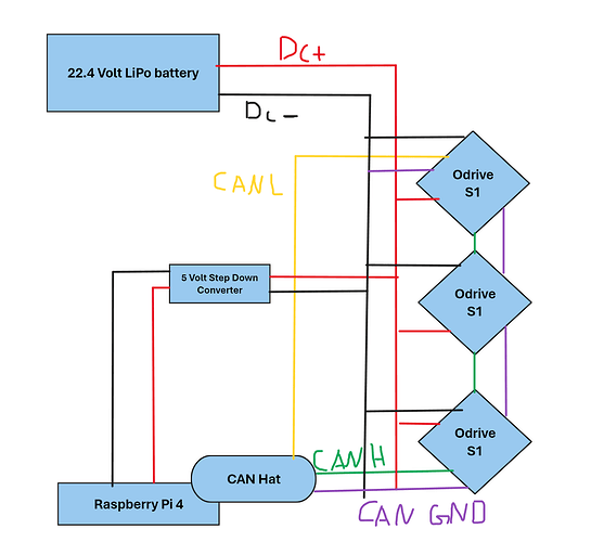
After reading the documentation and looking at other can diagrams on this forum and other forums, I drew out my own wiring diagram for my Battery, Raspberry Pi, Can Hat, and Odrives. However, I would like someone to verify that my plan isn’t going to harm or damage the hardware and that it would actually work.
Correct me if I am wrong, but the last Odrive in the CAN Bus has a built-in 120 ohms resistor.
A few things to note:
- Both CANH/CANL need to be daisy-chained through each ODrive
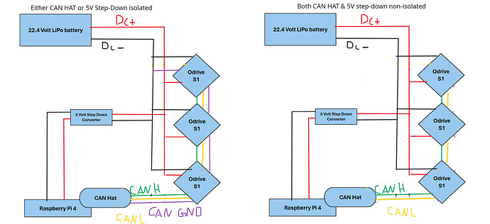
- You only need the CAN HAT to be connected to CAN GND (and thus a tie between CAN GND and DC-) if the HAT is isolated (like this one). If the HAT’s nonisolated (like this one), the HAT’s CAN transceiver will get its ground reference from the Pi GND, so (assuming your 5V step-down isn’t isolated either) you don’t need any connection from the CAN Hat to CAN GND/DC-.
- If you do need that CAN GND connection (5V step-down is isolated or your CAN HAT is isolated), then this diagram is correct however you only need a connection between CAN GND and DC- in one place – in this diagram it seems like it’s in two places.
Quick edited diagram, hope this helps:
Note the CAN GND and CAN 12V on the S1 are both passthrough inputs – they’re not connected onboard by default, so it’s fine to use something like the JST-GH CAN Cable that has the extra wires, even if you’re not using them.
1 Like

