Does anyone have any good connectors for high current DC that can be used with odrive?
I’ve been looking for some suitable connectors that can be used with odrive for connecting input power and motors but haven’t come across any. I have a mounting caddy with backplane For signals and I’d like to avoid soldering wires directly to the boards for easier disassembly.
Is the future v4 planning to include mountings for good connectors? Or should I design a board with a backplane connector for both power and signals? (Molex extreme energetic or amphenol pwrmax for example)
In the RC spectrum, you have the XT90 (2-pole) connectors for DC. The spacing between the centers seems to be 11mm and that seems to correspond roughly to the ODrive DC input. I have seen someone had soldered an XT90 to an ODrive, but I am not sure how good it will bind or how good the solder joint can or will be. Also, XT90 is rated for 90A “continuous” which may already limit you but it is also a RC connector that is tuned to be as small and as light as possible and only for typically handling very high currents a few minutes at a time, so depending on what you want to do, it may even get hot. You can search for Amass XT90, if you do not know them. They also make a three-pole inline connector for BLDC motors called MR, but I have not come across a larger variant than MR60 and the center-to-center spacing of the connectors seems to be too small for the ODrive’s motor outputs. For least resistance and highest current capacity, you may want to look into short pigtail cables of the highest possible cross-section terminated in large individual bullet plugs. These gold-plated bullet plugs come in all sizes and can easily handle any current in an ODrive system, depending on size.
I actually find that the MT60 connectors can handle a LOT more than 60A. They are more than twice as big as the MT30 connectors, and it’s more about the wire gauge that can fit in the cup, rather than a fixed rating,
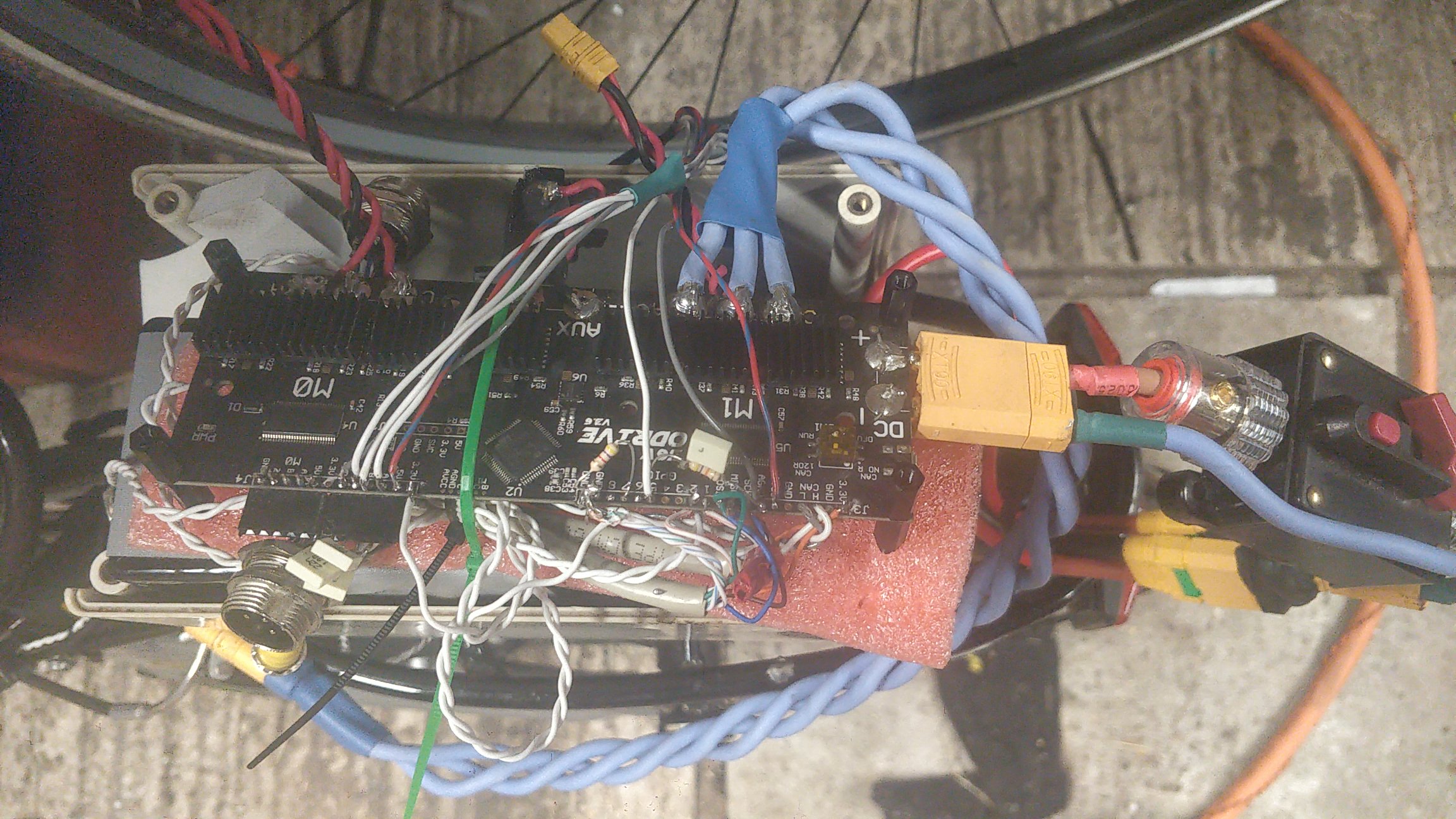
Here’s my ODrive, with XT90 input and MT30/MT60 output connectors:
I’m using 10AWG wire directly soldered to the board, which fits into the MT60. I have driven this (with a different motor!) at 100A without any signs of overheating the MT60
(ps. yes, I know the wiring/mounting is a bodge - I was testing it out to see if it can drive an ebike motor - it can )
I do now them. I’ve been thinking about using xt90’s for the power side. Though them being rc connectors I’m not sure how they handle in enclosed spaces and with prolonged usage. Ideally I’d like to use something rated for close to 100A for safety margin and maybe 6 or 4 AWG wire. Maybe something like these Phoenix contact blocks.
I’d actually be surprised if those Phoenix blocks are much better than MT60s. With a screw terminal you have a mechanical connection that can work loose (especially in a high vibration environment), and not all conductors are necessarily in good contact. Whereas solder (especially good old Lead solder!) tends to form a much more solid bond.
Also, in most use cases (i.e. at anything less than maximum speed and torque simultaneously) there is more current flowing through the motor wires than the power supply wires, due to re-circulation at less than 100% PWM duty. I can get away with a 10A fuse on the power input, despite driving my motor at 50A, for example.
That said, I wouldn’t advise to skimp on the power supply wire gauge, because you don’t want excessive voltage ripple putting noise into your system or straining the DC bus capacitors. This doesn’t apply to the motors, so your motor connector and wiring are only thermally limited.
The gold plated brass pins and sockets on the MT60 connectors are about the same width as 10AWG wire, and the wire itself acts as a heatsink.
I wouldn’t imagine you’d need anything much heavier than the motor winding tails themselves.
If you want to go full-on industrial, then use a crimped connector like Anderson Powerpole.
Another thing to note: In enclosed spaces and under prolonged usage, the ODrive itself will NOT handle 100A continuously on one axis, never mind two. The PCB itself is nowhere near as heavy gauge as 10AWG wire, never mind 6 or 4, and the FETs start to get hot around 80A. You will need forced air cooling.
Yes, the power input isn’t really an issue since it’s most likely just 40-60 amps. I’m more concerned with the motor phases. I’m also thinking could you run 5-10m motor phases and place the drives next to the power supplies away from the robot. Though I’m inclined to place the drives as close to the motors as possible for shorter cabling overall.
Phoenix stuff is generally really good so I have every confidence in those connectors. Powerpoles are also an option, they just don’t seem to have board options above 45A which limits me a bit. I still don’t like the idea of soldering stubby wires with connectors to the board.
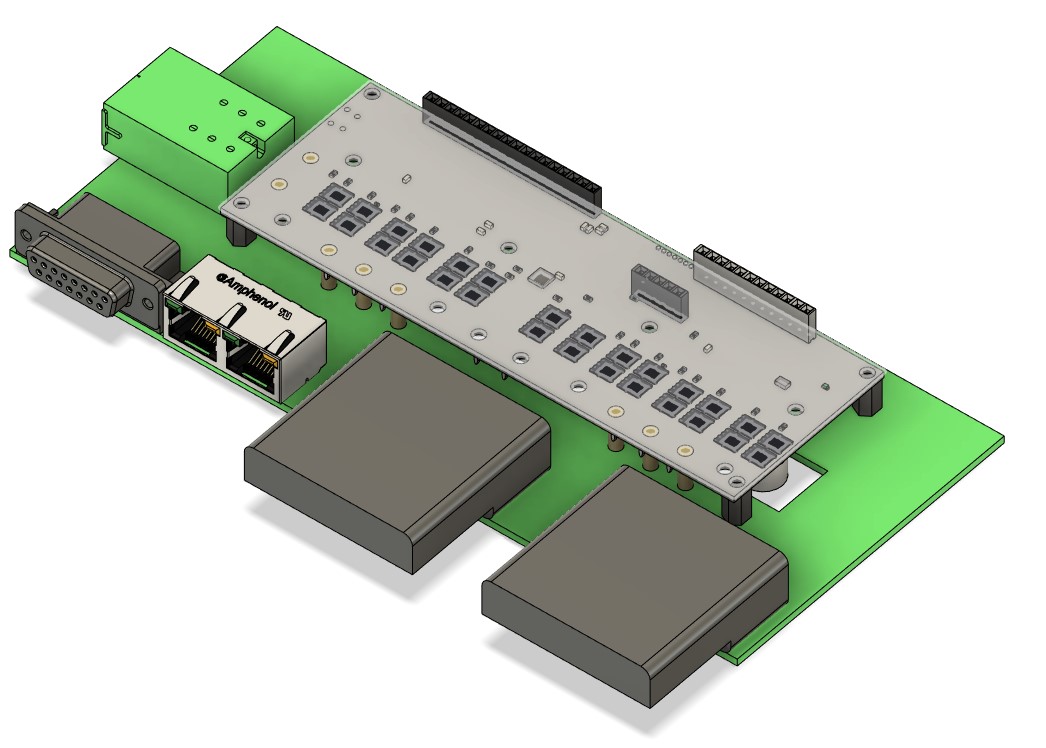
I threw together a mockup of a carrier board with good connectors(the big ones are SBS75G), bullets for power to the board and signals broken out. The board would also have isolators and differential drivers for encoders, uart and spi. The RJ45s would be encoders, the db15 for everything else.
can’t decide if i want to use spi encoders or not.
if you’re using RJ45, does that mean you are using differential signaling on your encoders? Otherwise you might as well stick with the DB15s?
I am using DB9 connectors for a combination of SPI and incremental feedback. There’s just enough pins for the SPI along the top row and incremental along the bottom. All single-ended though.
Industrial encoders would of course use RS422 differential signalling for everything - both for serial (SSI/BiSS etc up to 2MHz clock) and incremental encoder interfaces, and yet DB15 is a common choice for a feedback connector at the drive end. On the motor end they tend to be “M32” style circular connectors.
At first I thought your dual RJ45 might have been part of an EtherCAT mod
What’s the big green power connector in your sketch?
I think the SPI encoders (or ideally SSI/BiSS but ODrive doesn’t support that) are a much better option than incremental encoders. No calibration on start-up (so you can have a heavy load that would otherwise upset the calibration) and allows for cogging compensation to work properly.
However, myself and a few others have been having issues with AMS SPI encoders recently. We’re getting an error flag back from the encoder when the motor turns on, and the ODrive does nothing to reset it.
Therefore I think a combination of SPI and incremental interface from the AS5047 and similar might be best. Absolute value read over SPI at boot to avoid calibration, and incremental used thereafter.
Yea the signals on the board are all differential. Encoders are isolated with IL613-E isolators that work also as differential termination drivers. It’s also voltage agnostic. Though I have to deside what I want to do wince the drivers are one way.
I’m going to do ethercat with easycat+teensy, that way I can control multiple boards and I don’t have to learn stm32 programming.
I really like rj45s for signal transfer. Compact, right amount of pins and cheap. I was thinking of putting rj45s for differential uart and spi but figured it might get confusing. I may use rj11 for uart and something else for spi. Depending on what differential transmission I do. Maxim has ics that do spi over single twisted pair at 1MHz for 10m, might use those or plain rs422 drivers. The downside to this is I have to build a board for the encoder side too.
I would like to use SPI encoders but we’ll see where I’ll end up. Let’s hope they can sort that problem.
The big Green one is just a Phoenix high current plug terminal. I might put a 4 pole terminal in there for daisy chaining the power to adjacent drives.
Researching this has made me desire a higher voltage though. Upping the voltage would bring the current down conciderably and make wiring all the more easier.
I’m also thinking of putting the io connectors on a separate board and routing them with a flat cable to the main board. Would give me some extra design room since I can increase the thickness of the package more than length or width.