I’m still here and have the 9 boards that I will soon be using for my mill project, although now I will be running a Teensy 4.1 to control the ODrives via your boards.
I’ve been a little tied up with a heart op, moving and changing my main job, but back on track now.
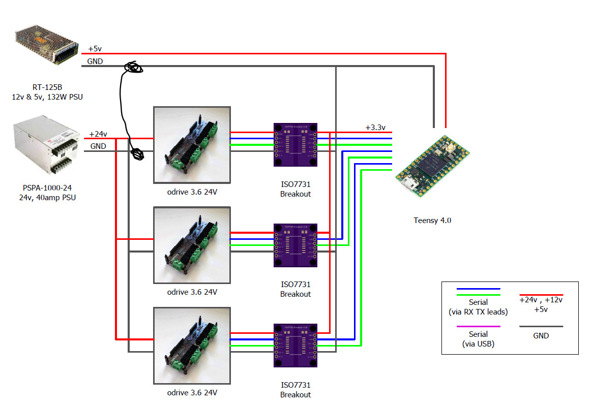
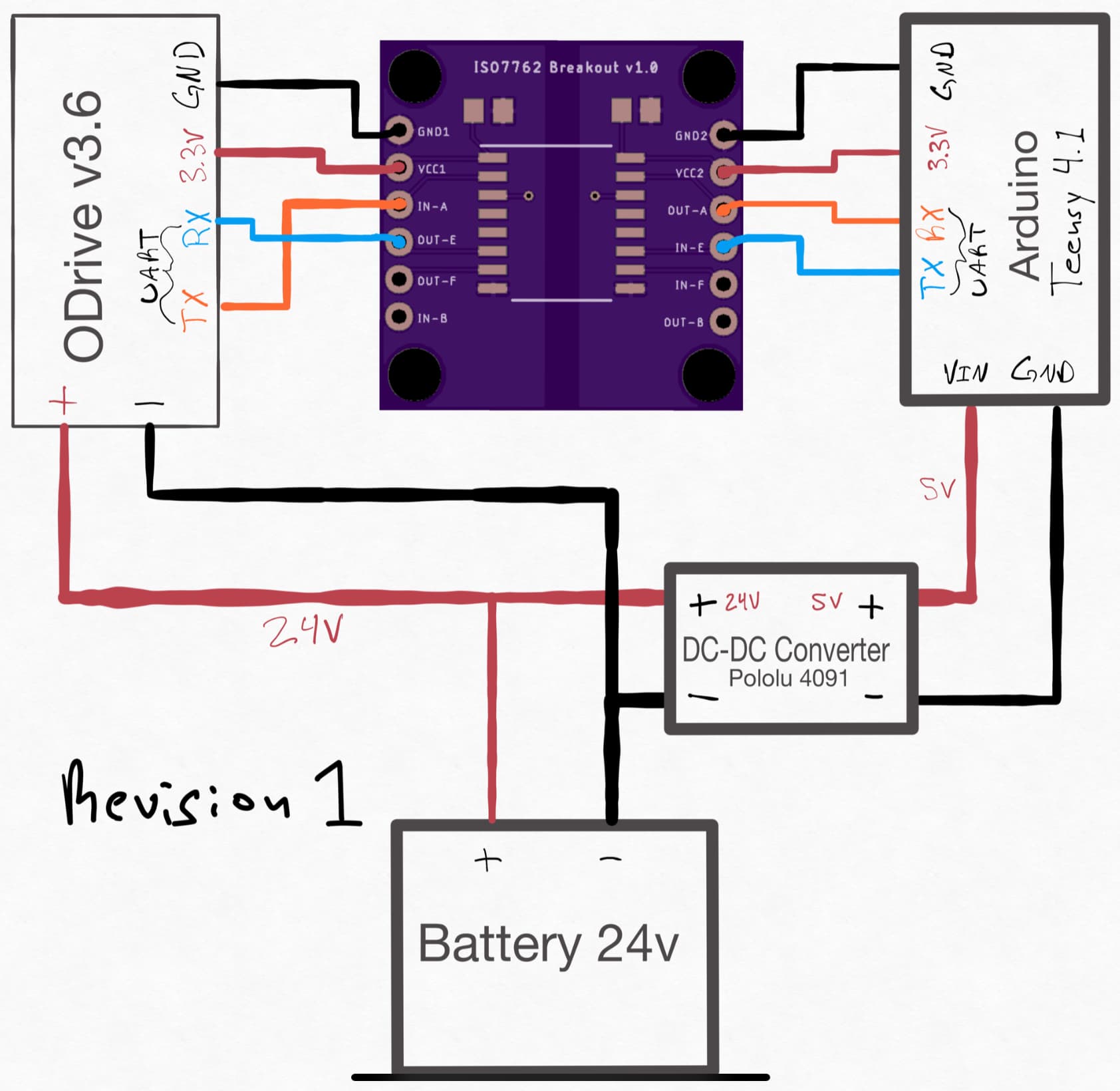
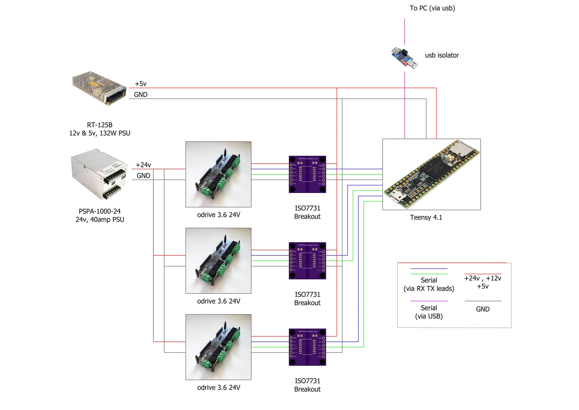
Hi @Alexander_Jones@danbowen95@Wetmelon , I’m looking to implement the ISO7763 UART Ground Loop solution and was hoping to get some clarification/second set of eyes for the schematic necessary to use it correctly. Please see the following, any feedback is much appreciated!
I now have this chip in and working on the breakout board above, they are awesome and brings such piece of mind when running the ODrive at higher currents.
I will make sure I get a USB isolator too, just in case I forget and plug both Teensy and ODrive into the same PC.
Here is a link to my video with it all working well: -
I’m really struggling to get my isolator boards to work (Using ISO7731 chips) - although they might not be the issue. Reading voltages is not reliable (see here) and when I go to calibrate the motors via the arduino example script, the motor often does nothing, but sometimes makes a screeching sound before calibrating, but never entering closed loop control.
Couple of questions:
Am I missing something really simple…?
Is it worth grounding the two separate PSUs?
Is it worth getting ferrite rings for the cables - the motor cables are quite long at around 2m from odrive → motor
Do I even need these isolator boards? Each of my motors pulls at max only around 2amps and since the teensy is powered by a separate source, it’s only the battery loop causing the ground loop, and this loop is physically quite small, see below. I’m scared to try without in case I fry something!
Looking at your setup, I would highly recommend this.
CAN is much less hassle than Arduino in my experience. You can drive it straight from Python on a raspberry pi OR a windows or linux PC, and the ODrive CAN protocol is dead-simple.
Just one isolated CAN transciever is all you need, you can throw out the ISO7762 boards and use one of these: https://www.inno-maker.com/product/usb-can/
CAN is designed for this sort of thing and is MUCH more robust to noise than any UART.
Also, please buy some ferrite rings. They will help a lot.
One more point: Those brake resistors are a potential fire hazard if you mount them directly to the MDF. I would mount them on standoffs like you have done with the PCBs.
Another minor point: since you are using 24V ODrives with a 24V PSU, there’s very little headroom for the brake resistors to limit the voltage to a safe level for the ODrives. If you have an adjustment pot on your PSU, please turn it down to 22V or so. The 24V ODrives cannot handle anything above 24V.
It looks like it’s time to bite the bullet and start looking into CAN! The guide @Wetmelon has suggested previously in this thread should be a good start. I’m only looking to move 5 motors using the trapizoidal trajectory control method so hopefully it shouldn’t be too tricky.
Yes, thanks for pointing this out!
Yes, much like implementing CAN from the get go, hinesight is a wonderful thing and I absolutley should have gone with the 56v versions. I’ve turned the output voltage from the PSU to 23v.
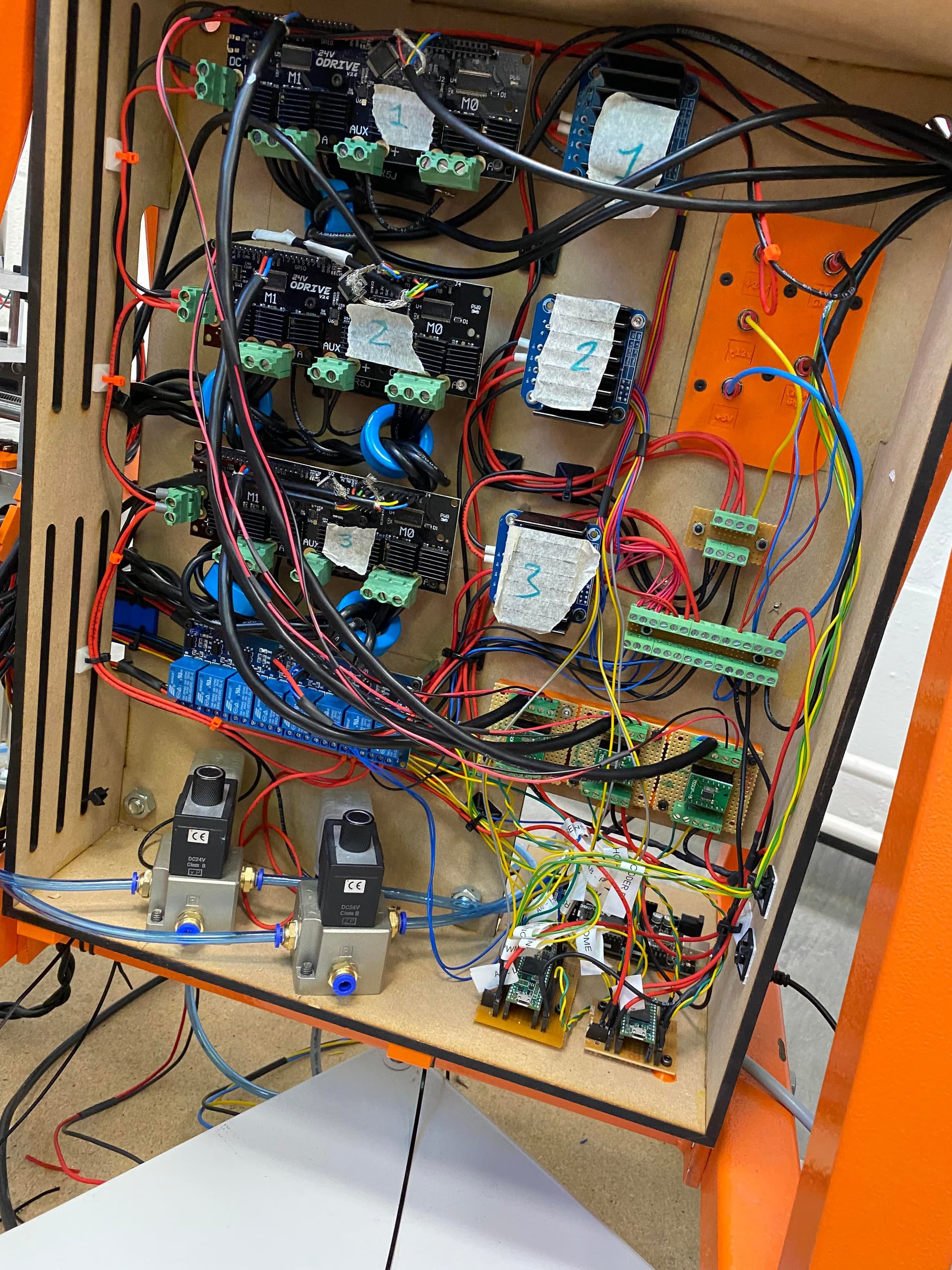
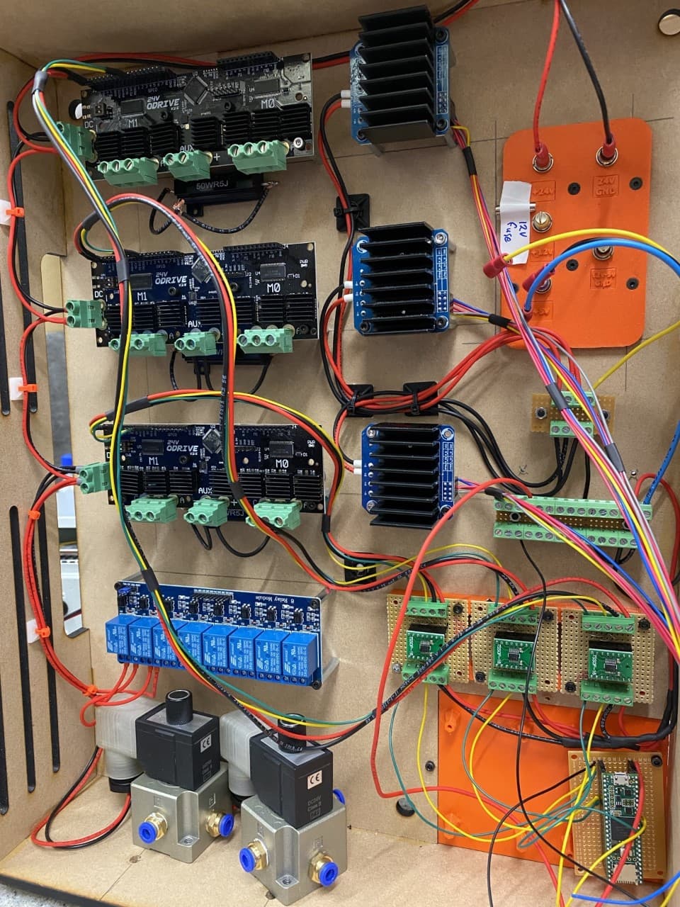
I’m really struggling to get the system to work reliably :(.
There are no issues when moving the motors using the odrivetool, but when controlling them using the serial connection (through the teensy) the motors cut out after a short period of operation (around 5 mins). The operation consists of sending set position commands to two of the 5 motors at 25ms intervals (not going very fast or under any particularly high load).
I’m almost certain it’s a noise issue. Above is what cabinet looks like now. I’ve shielded the serial cables from the isolators and the odrive and twisted the wires from the teensy to the odrive but the problem persists.
Any suggestions on how the noise can be further reduced or any other pointers to what the problem might be? Would it perhaps help if i joined the grounds as shown below:
If you can; try one odrive at a time. If that passes add another odrive to the test.
If it happens always at the same point in the teensy program may be the teensy or the program?
In my projects I use 24 volt battery packs with a 5v buck converter for my controller. I have always been suspect of bench power supplies for multiple-motor projects.
Good idea. Thinking about it systematically, the motor plugged into the top odrive (labelled 1) has never shown issues. It might be then, that the three wires coming from odrive 1 might affecting the serial wires into the odrive below, since they’re mounted so close? Similarly with odrive 2 and 3?
This means the grounds are connected (?). I’ve read that it helps to have common ground, but am scared of creating a ground loop and frying things!
UART (I think). Here’s a snippet of code that works fine, before the motors goes into an error state
Relevant preamble:
/// Libraries
#include <HardwareSerial.h>
#include <ODriveArduino.h>
.
.
.

/// Odrive helper
template<class T> inline Print& operator <<(Print &obj,     T arg) {
  obj.print(arg);
  return obj;
}
template<>        inline Print& operator <<(Print &obj, float arg) {
  obj.print(arg, 4);
  return obj;
}

// ODrive objects
ODriveArduino odrive1(Serial2);
ODriveArduino odrive2(Serial3);
ODriveArduino odrive3(Serial4);

// General Machine settings
float linespeed = 20;  // mm/s of linespeed
float arcspeed  = 1;   // mm/s of arc
float homespeed = 5;   // mm/s of homing speed
float dt = 25;         // how often do we send motor positions (millisecs)


void setup() {
  /// Start serials
  //Serial.begin(9600);             // To PC (for debug)
  Serial1.begin(9600);            // To master controller

  Serial2.begin(115200);          // To odrive 1
  Serial3.begin(115200);          // To odrive 2
  Serial4.begin(115200);          // To odrive 3
}
Example function to drive two motors:
void A3A4Arc( float thetaEnd ) {
  /* Move Axis 3 and 4 at an arc
  */


  // Some vars
  int Tmove;             // How long are we running for (given dist & spd)
  float A3PosFinal;      // Final position of A3
  float A3MotorPosFinal; // Final motor position of A3
  float dA3;             // Increment position of A3
  float A3RevFinal;      // Final A3 motor position (Revs)
  float A3RevPos;        // Temp pos of A3 motor as it moves (Revs)
  float A4PosFinal;      // Final position of A4
  float A4MotorPosFinal; // Final motor position of A4
  float dA4;             // Increment position of A3
  float A4RevFinal;      // Final A4 motor position (Revs)
  float A4RevPos;        // Temp pos of A4 motor as it moves (Revs)
  bool Done = false;     // For breaking the while loop
  bool Good2Move;        // Can we move?

  // Time
  unsigned long runTime;    // Current running time
  unsigned long startTime;  // The time we start moving
  unsigned long endTime;    // The time we expect to end

  // For geometry
  float R;            // Arc radius
  float theta;        // floating varible
  float thetaStart;   // Starting value of theta
  float thetaInc;     // Total theta increment
  float thetaRate;    // Angular velo

  /// Do some initial calcs
  R = sqrt((A3Pos * A3Pos) + (A4Pos * A4Pos));

  // theta calcs
  thetaEnd   = min2Rad(thetaEnd);
  thetaRate  = arcspeed / R;             // v = wR
  thetaStart = tan( A4Pos / A3Pos );
  thetaInc   = thetaEnd - thetaStart;

  // End positions
  A3PosFinal      = R * cos( thetaEnd );
  A4PosFinal      = R * sin( thetaEnd );
  A3MotorPosFinal = A3MotorPos + (A3Dir * (A3PosFinal - A3Pos) * A3Rpmm);
  A4MotorPosFinal = A4MotorPos + (A4Dir * (A4PosFinal - A4Pos) * A4Rpmm);


  /// Do a bunch of checks to see if we're good to go
  Good2Move = axisCal( 3 ) * axisHome( 3 ) * axisCal( 4 ) * axisHome( 4 ) * withinLims( 3 , R ) * withinLims( 4 , A4PosFinal ) * withinLims( 0 , thetaEnd );

  // Are we good to move it move it?
  if (Good2Move) {
    // I like to move it, move it

    // How long will the move take, for the given speed
    // Note:  - linespeed should ALWAYS be a factor of 100 AND <= 100.
    //          (1,2,4,5,10,20,25,50,100 mm/s)
    //        - resolution of dist = XXX.X (mm)
    //        -> therefor, Tmove ALWAYS an int (millisec)
    A3PosFinal = roundNum( A3PosFinal , 1 );
    A4PosFinal = roundNum( A4PosFinal , 1 );
    Tmove =  1000 * abs(thetaInc)  / thetaRate;

    // Work off time:
    startTime = millis();        // The time we start moving
    endTime   = startTime + Tmove;

    while ( !Done ) {
      // calc runtime:
      runTime = millis() - startTime;

      // Calc change in position
      theta = thetaStart + (thetaInc * (float(runTime) / float(Tmove)));
      dA3   = R * ( cos(theta) - cos(thetaStart));
      dA4   = R * ( sin(theta) - sin(thetaStart));

      // Calc changes in motor position
      A3RevPos = A3MotorPos + (A3Dir * dA3 * A3Rpmm);
      A4RevPos = A4MotorPos + (A4Dir * dA4 * A4Rpmm);

      // Send to position
      odrive2.SetPosition(0, A3RevPos);
      delay(dt);
      odrive2.SetPosition(1, A4RevPos);

      // If within dt of Tmax, send to final pos:
      if ( runTime >= Tmove - dt) {
        // Send to final position
        odrive2.SetPosition(0, A3RevPos);
        odrive2.SetPosition(1, A4RevPos);

        // Update some values
        A3MotorPos = A3MotorPosFinal;
        A4MotorPos = A4MotorPosFinal;
        A3Pos = A3PosFinal;
        A4Pos = A4PosFinal;

        // End
        Done = true;
        break;
      }
      else {
        // Wait for motor to catch up and serial to clear
        delay(dt);
      }
    }
  }
}
Okay, that’s UART Ascii. You are using 0.5.1, which has a stupid bug in that it sends both ASCII and Native responses, which can cause the client to stop working after a random amount of time. I suggest to update the firmware. If you want to stay on 0.5.1, I can show you which code to change to fix the firmware.
Sounds promising! It is probably easier if I update the firmware, right? I can’t think why i should need to stick with 0.5.1. I’ll update tomorrow and get back to you. Thank you!
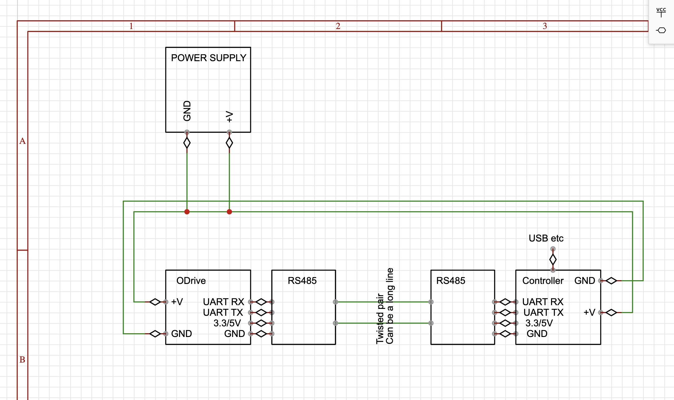
I think you could be looking for RS485 interface. You will still be able to you whatever software using UART you already have, on both ODrive and your controller side, and RS485 will give you long, interference resistant, ground decoupled and cheap communication lines.
RS485 chips could be as cheap as $0.15 per piece if you buy ~dozen at once, any extra components around will be a few cents more (unless you want to go for a true high voltage isolation etc).
Software won’t even notice it’s not a plain UART anymore, you won’t need to change anything at all.
Note RS485 is a differential signal line, you don’t need to run a 3rd “ground” line in between two RS485 modules.
Edit: or you can get pre-made UART <> RS485 boards for like 50 cents each if that’s the way you prefer.
Edit: Please ignore the PSU GND shorted to a positive voltage, that was a quick sketch
Make sure you have the ferrite rings on the motor phases. It dramatically reduces the noise.
You shouldn’t have to ground those two power supplies as shown, although I don’t think that would cause issues (since the comms lines themselves are still isolated)
I hope this message finds you well. I came across your excellent ISO7762 Basic Breakout board design on OSH Park (OSH Park ~), and I’m very impressed with your work.
I’m an electrical engineering student working on a robotics project that requires UART isolation to prevent ground loops between multiple ODrive controllers and a Jetson Nano. Your ISO7762 breakout board appears to be exactly what I need for this application.
Would it be possible for you to share the design files (Gerber files, schematic, or KiCad/Eagle project files) so I can manufacture the boards through PCBWAY? I’m looking to order a small quantity for my senior design project.
I completely understand if you prefer to keep the files private, and I’d be happy to order through OSH Park if that’s your preference. However, having the files would allow me to potentially make minor modifications for my specific application and would be greatly appreciated.
Thank you for your time and for contributing to the open-source hardware community. Your design will be very helpful for my project.
I’m working on a project using the odrive_milana fork (inspired by the Milana Robot project-GitHub - helmutbuhler/milana_robot) and need to implement UART ground loop isolation between my Jetson Nano and multiple ODrives.
Does anyone have PCB design files (Gerber/KiCad/Altium) for a UART isolator board that I could order from PCBWay? I’d prefer something that’s been tested and works reliably with ODrive UART communication.
Alternatively, if there are better off-the-shelf solutions with equal or better performance, I’m open to recommendations.
My requirements:
Support for 115,200 baud (or higher)
Multiple channels preferred (connecting several ODrives to one Jetson Nano)
Any help with PCB files, tested schematics, or recommendations would be greatly appreciated!


 They will help a lot.