Hi folks,
I’m running BLDC gimbal motors with high winding resistance, and I’m getting a mismatch in the phase resistance measured by the ODrive vs. measured by my multimeter.
(Assuming star winding configuration,) I measure 16.6 [Ohm] between motor wires with my multimeter. Divide that by two to get a phase resistance of 8.3 [Ohm]. But after ODrive calibration, odrivetool replies with odrv0.axis0.motor.config.phase_resistance at 2.53[Ohm]. Does anyone know where this inconsistency could come from? (Maybe these measurements are made in the DQ frame, or some other 3-phase trickery?)
Full disclosure: I repopulated the shunt resistors with 80 [mOhm] ones assuming the 16.6 [Ohm] winding resistance. I also changed SHUNT_RESISTANCE to 80e-3f and recompiled and flashed the firmware. Other possibly-related config settings are:
odrv0.axis0.motor.config.pole_pairs = 14 # 24N28P
odrv0.axis0.motor.config.requested_current_range = 2.0
odrv0.axis0.motor.config.motor_type = MOTOR_TYPE_HIGH_CURRENT
odrv0.axis0.controller.config.vel_limit = 10.0 # RPS
odrv0.axis0.motor.config.resistance_calib_max_voltage = 2.0
odrv0.axis0.motor.config.calibration_current = 0.7
Is there anything else I’d need to change?
Cheers–and thanks for taking a look!
Lastly, this other thread on shunt replacement looks like a similar problem but without a solution just yet.
You need higher resistance_calib_max_voltage.
V = IR = 0.7A * 8.3\Omega = 5.81V
Ahh, ok. I think I have a better understanding what the settings are doing.
To double check, is the the calibration procedure trying to hit the calibration_current and then reading the resulting voltage to determine resistance? And if the resulting voltage exceeds resistance_calib_max_voltage, it errors out?
Assuming that’s the case, I decreased the calibration_current to 0.4[A] and increased the resistance_calib_max_voltage to 10[V]. The motor calibrates without errors, but the system still measures 2.53[Ohm] as the phase resistance.
After squinting at how the test voltage is computed to calculate R, it looks like this is just a filtered value that eventually uses Ohm’s law like you have above. Following a related post, I can confirm that the op-amp gain is correctly being set to 10 (lowest setting) by checking thatphase_current_rev_gain returns 0.1, which is 1.0f / actual_gain. Given that I changed the actual board shunts and then SHUNT_RESITANCE in the code, I have a weird feeling that I’m leaving something out that’s resulting in the wrong measurements.
Finally, I need to mention that these motors (GM110-08) have a huge number of windings. I needed to bump up the phase inductance limit in firmware to prevent calibration from failing with MOTOR_ERROR_PHASE_INDUCTANCE_OUT_OF_RANGE.
Yeah you understand it. If you’ve changed the shunt resistance values, everything should be ok. Is it possible the shunts are the wrong value, or not soldered properly? Or you multimeter sucks? 
Ok, for a sanity check, I
- checked my multimeter against some 6.8[Ohm] resistors and got 7.1[Ohms], so I trust the multimeter.
- restored the old firmware and calibrated the motor on axis1 which still has the old shunts populated. (I only replaced the shunts on axis0.) In this configuration, now I get 2.71[Ohm] phase resistance as measured by the ODrive.
That second test (old code + old shunts) is super confusing. Something about introducing a motor with really high resistance and inductance even with a vanilla setup is giving sketchy resistor values. Would a motor like this take longer to get a stable measurement? I think the measurement times for measuring phase resistance and inductance are 3000 [ms] and 1250 [ms] respectively.
Also: is there anything wrong with just changing shunt resistors on just one axis if I’m just using one motor?
I’m trying to dig into how phase resistance gets measured, and I’m still puzzled on how test_voltage_ gets computed. From the source code, it looks like some flavor of State Observer or IIR filter: v_{k+1} = Ki_{target} - Ki_{k} + v_k where K = k_I \Delta t. Here k_I = 1.0 and \Delta t = 0.000125. The comment says that the units on k_I are \left[ \frac{V}{s \cdot A} \right], which makes me think that the value of k_I should change if the sense resistor value changes also. If there’s any writeup on where these calcs come from, I’d gladly look into it!
No, nothing wrong with it. But it does feel like you’ve somehow plugged into the wrong one
Ok, I’m onto something. First, I’ve confirmed that everything’s wired/configured correctly. (No flipped shunts.)
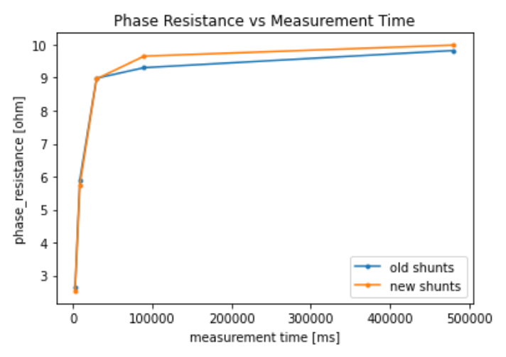
Ok, so this looks like the right path. I tried a bunch of wait values besides that 3000 [ms] value above, and plotted the resulting phase resistance for two types of shunt resistors. (Oof, lots of firmware uploads.) Here’s the result:
This makes me think that the phase_resistance measurement code is “bailing early” before the measurement settles, and it explains the lower-than-normal value. I’m guessing(?) that motors with low phase resistance values (on the order of a hundred milliohms) don’t take long to get a stable measurement, but motors with a higher phase resistances (on the order of tens of ohms) take much longer according to the current code.
I should mention that I have a PSU that displays the current draw on the front. For smaller wait times (up to 30 seconds), I can actually see the current draw slowwly ramp up to the calibration_current value, but never reach it.
For my own purposes, I can hack the code and add a big wait time for calibration. But this maybe looks like a bug if the measurement code bails at an arbitrary point in time without knowing if the measurement has settled?
Finally, I’m getting a settling value of ~9.9ish [ohms], and that’s still different from the ~16.6/2 = 8.3[ohms] I get from my multimeter, so I’m guessing this isn’t the full story? Above measurements also seem to be sensitive to my chosen value of calibration_current. (Both runs were taken with calibration_current = 0.8 for both shunt types.)