Quadruped Design: Encoder placement & no recalibration

Hello all!

I have decided to pursue the challenging road of designing my own quadruped. I am in the early stages of designing the kinematic linkages and was trying to aim for a design that did not require a recalibration after every boot with homing switches, as well as having an incredibly small backlash as to not complicate the inverse kinematic equations and control system that much.

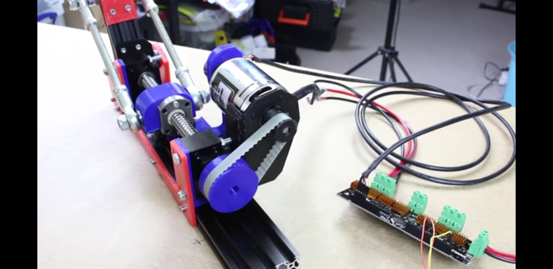
After some searching, I found a guy on YouTube named Steve Bruton who built his own quadruped. He is using a belt and a ball screw to drive the links which I thought was pretty smart since it facilitates virtually no backlash. In addition to almost no backlash, I would think having a ball screw would give the joint more resistive torque since the direction the force needs to primarily act in to get the joint to bend is radially (i.e. bending the joint directly would mean that your forcing the slider to work its way up the ball screw which seems difficult to do unless your turning it radially). Below is a video and picture of Steve Bruton’s linkage mechanism:

I would like to implement something similar in my design, however, unlike Steve Bruton’s design, I would really like to not have to recalibrate after every reboot with limit switches. So my question is, how exactly can this be done?

I know the topic of not recalibrating has come up in several thread discussions here, but I thought this problem was slightly different given the gear ratio with the belt drive and the ball screw. I was thinking of using an absolute encoder at the joint instead of on the motor. I know there is sort of support in the firmware in the future branch for absolute encoders, but thought it would be even trickier with absolute encoders that were dissociated with the motor; this is because it seems like the firmware has mainly been tested not only for incremental encoders, but for encoders that are attached directly to the motor.

I may be wrong, but at first glance there seems to be additional benefits feeding encoder values directly into the odrive since it seems to use the encoder as a feedback system to give you some good control over the motor (as well as various other metric values about the motor?). I would ultimately like to leverage as much as the odrive has to offer so I am not reinventing the wheel.

The odrive encoder documentation describes resolving the issue of constantly having to recalibrate at every boot by using an encoder with an index signal. If I attach the encoder directly on the back of the motor, this doesn’t seem like it would do me much good because it seems like the index can only be found within a particular revolution. Given the increase in ratios with the belt drive AND the ball screw, being within one rotation on the motor will not map well to the actual joint.

Alternatively, I can place an encoder with the trigger signal on the actual joint instead of on the back of the motor, but if I pass the encoder values to the odrive, will it be able to make sense of it and provide all the features it normally would if it were attached on the back of the motor.

Please let me know if I missed something or am misunderstanding anything. Any suggestions would be incredibly useful and greatly appreciated. Also would love to hear any criticism on using a belt drive with a ball screw for a quadruped.

Thank you!

In my opinion, a ball screw is a really bad idea for this design. Bruton himself has since revised his quadruped design and replaced the ballscrews with a more conventional spur gear design that allows for compliance/force sensing: https://www.youtube.com/watch?v=bHCzrDr-t3w

Just about every modern quadruped uses the same basic idea: pseudo-direct drive actuators, consisting of a large-diameter, low-height brushless motor and a low-reduction (5-10x) planetary gearbox. This provides good torque density while retaining (most of) the dynamism and force transparency of a direct drive actuator. You can read about the principles behind this design here: https://dspace.mit.edu/handle/1721.1/118671
The OpenTorque actuator (on hackaday) is a good example of this design.

I recently built one such quadruped myself; you can read about it here: Experimental Quadruped with 3d-printed gearboxes

As for your question about encoders - high end quadrupeds have two encoders per axis: one for electrical angle (attached to motor output shaft) and one for axis angle (attached to gearbox output shaft). The latter is used to determine the absolute angle of the joint without requiring limit switches or any such hocus pocus.

2 Likes

Hi Mike,

Thank you for the great info. I didn’t realize Bruton was working on a redesign. I also read a good portion of the MIT thesis and how they went about actuator selection. The overall notion of using the largest possible motor with the smallest possible gear reduction makes total sense and from what I have been reading and what you’ve said, gives you a lot of benefits for applications like quadrupeds; I’m definitely sold. I’ll start keeping an eye out for pancake style, low KV, high torque, brushless motors. Any suggestions on any motors or vendors you think I should look at? I have been looking at Turnigy motors similar to this one:

9235-100KV Turnigy Multistar Brushless Multi-Rotor Motor

As for the encoders, I was sort of afraid I’d have to resort to two encoders (one attached to motor shaft and one after gearbox). I was trying to prevent all the cable routing and additional power consumption that comes with adding another set of encoders on all the motors :persevere:

The quadruped you designed is incredibly cool! Do you have an encoder before and after the gearbox as well? Are you feeding the encoder values into the Odrive, or are you passing the encoder values to your main processor to do the calculations there instead. If you are passing the encoder values to Odrive, are you using its trajectory generation and tracking capability, or are you handling trajectory planning/generation in your main processor? I saw on hackaday that you were using a Cortex-M7 processor. Are you doing bare-metal or are you implementing an RTOS on the ARM chip? Is the Cortex-M7 the only processor that is controlling the quadruped?

Thanks again for the input and knowledge!

That motor is a great option.

Encoders have a very modest current draw; with motors of this size, the power consumption of encoders is negligible.

At the moment, I only have encoders on the motor output (electrical angle); I will probably end up adding the secondary encoders, but I’m also considering using IMU’s on the thighs since they provide implicit hip & shoulder output angle values (and, at $20 total, it’s considerably cheaper than the ~$200 required for 8 encoders). Still, I’m not sure it’s worth complicating the design when a conventional design with secondary encoders will do the job fine.

The Teensy 4 is indeed the only microcontroller onboard the robot (except for the 6 odrives). The Teensy communicates with the odrives over high speed UART. IK & realtime control calculations are done on the Teensy; high level body/leg commands are fed to the Teensy via USB/UART.

1 Like