Hi!
(Plan B, since can-bus control is way over my head)
I want to use an output from a MaxxECU Race unit to control my ODrive (which controls the BMW x-drive clutch).
The ECU is outputting a GND control signal, and as I understand, the ODrive will need an active high signal.
If I use a pullup to 3.3v (right, og 5v?), I would need to invert the signal from the ECU, so that the OFF (pulled up) period equals the period I need for ON signal to the Odrive?
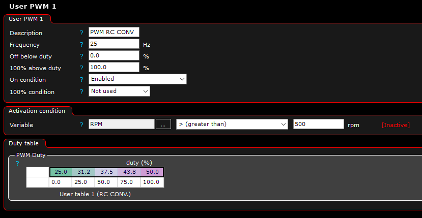
I figured that a frequency of 25hz would be suited for RC Servo PWM, giving a period of 4ms.
Since lowest value in RC PWM is;
0% movement = 1ms
50% movement (center) = 1,5ms
100% movement = 2ms
In order to achieve this from the ECU, I will set the output duty cycle to:
0% movement = 1ms = 25% DC.
50% movement = 1,5ms = 37,5% DC.
100% movement = 2ms = 50% DC.
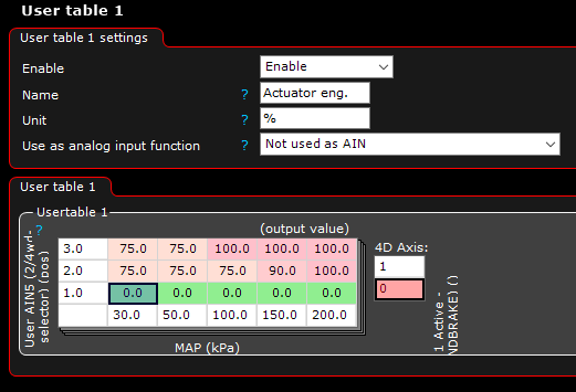
At first, in the ECU software, I put the control critereas into one table, where 0% equals open clutch, and 100% equals locked clutch.
Then, in another table, I map the DC signals to match the output wanted (for easier tuning)
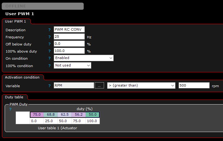
But for this to work, with the going low (GND) output of the ECU, I will need to invert the low signal to a high. Because when the output is active, the odrive sees the low signal, and when the output is not active, Odrive sees the high signal right?
So my mapping table should be opposite, like this?:
RC PWM is 50Hz, why change it? We sample at 50Hz so in the first sample you’ll be 100% duty cycle then in the next sample, 0% duty cycle. So you probably won’t move at all. Just set it to output 50Hz and then follow the RC PWM docs https://docs.odriverobotics.com/interfaces#rc-pwm-input
You can always invert the commands on the odrive side (set the 100% mapping to negative output and vice-versa) if you want to flip it there, or you can set it on the ECU side. Either will work.
Just did it because the google docs I found didn’t specify it, only the 1ms to 2ms on times.
So I figured 25hz would give better resolution, but if 50hz is the way to go, no problem for me
I mixed some terms in the initial post, so needed to correct myself 1sec is 1000ms, not 100
So to clarify stuff; if i set frequency to 50hz, each period will be 20ms, and then;
10% dc (2ms) will be equal to the RC servo 100% movement.
7,5% dc (1,5ms) will be 50% movement.
5% dc (1ms) will be 0% movement.
Since the output from my ecu is a ground signal, (who I need to pull up to 3,3v to look like a high signal when output floating) the output signal to give 100% movement (10% dc), will actually be 90%, and for 0% movement (5% dc) it will be 95%
And another thing.
Is it possible to program the odrive to output a pwm signal that is related to measured encoder position? Or measured motor current?