This is the step/direction thread, where we discuss the requirements for this interface, and try to come up with a good solution.
Since step/dir comes up in many other threads, this thread will have a fair bit of content moved to it, so please excuse the destroyed contexts.
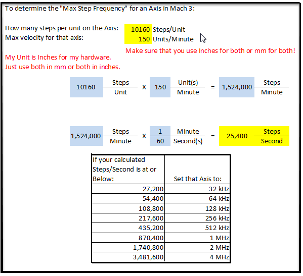
So how fast must a step/dir interface be? Say we can do 1 Mhz and there are 4000 steps per rev. Only 250 rpm  why not simply use 10 or 20 Mhz?
https://warp9td.com/index.php/faq/faq-mach3#MachThreeStepFreq
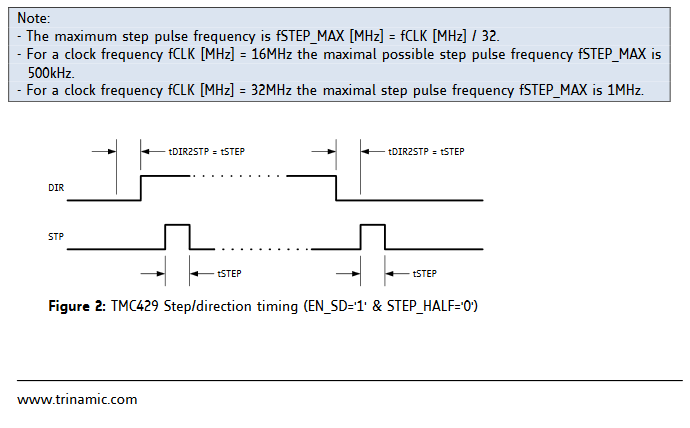
https://www.trinamic.com/fileadmin/assets/Support/Appnotes/AN016_TMC429_TMC26x_Getting_Started.pdf
Be careful with your units. 1 MHz / 4000 steps/rev = 250 rev/s = 15,000 RPM.
1 Like
a step rate of 125KHz is considered extremely fast, with a typical 200 step/rev stepper motor that is 625 revs/sec or 37K rpms
most interfaces won’t be able to do 1K rpm (~3KHz step rate).
now, with the odrive, we are talking 2400-4000 counts/rev, not 200 steps/rev, so the rate we would need is about 10x that.
This is a burden on both the system generating all these step pulses, and on the odrive trying to receive and process all these pulses (and remember, the odrive can’t know if a slight variation in the generation frequency of the pulses is intended and should result in a change in speed, or if it’s due to the limits of the sender)
that’s why it’s FAR better if we can figure a way to be able to use a higher level protocol like the serial one that’s in place.
Ups…250revs/sec seems fast…ups 
Anyway, 1 Mhz is a clock that is not critical for the timers/counters of our MCU. And there are plenty of them. We just need
- a timer that is large enough (32bit?) to get sufficient resolution and catch overflow events
- An Interrupt that calcs pulse frequency and stores it in a circular buffer that contains just pulse event timestamps, where positive values represent commands in positive direction, negative ones in the other direction. Each timestamp represents just one pulse. A ring-buffer of some hundret bytes of RAM should be fine…maybe even DMA could be used here for speeding things up/ keep CPU load down.
Velo and accelerration can then be calced from those pulse event timestamps.
just a short piece of code no? A 32 bit timer can count to 4*10^9, that is 25 seconds at 168 Mhz (prescale faktor 1) till it overflows…thats more than plenty! I think the the EthernetSmothstepper has equally performand hardware on its FPGA
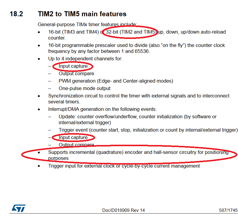
STM32 F405 Datasheet
TIM2 and TIM5 are 32bit ones (page 32)
If resolution of both sender and receiver are fine enough, the errors become very small:
Please also have a look into the reference manual fo the STM32F405 on page 587:
The Step/Dir interface isnt so different from a quadrature interface. Maybe we could support both later for the use with LinuxCNC: Step types supported by LinuxCNC
Step/Dir is an industry standard that is a must for every AC servo driver. Sure a high level interface would be superior. Maybe something very basic like a 32bit SSI Graycode Interface would be a good start
Short question on this, which are the pins foreseen for the step/dir Signals on the board?
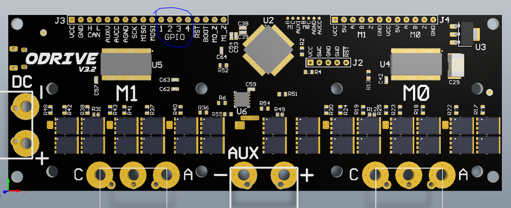
Ok, so we’re quite tight on pins  normally there is also one enable pin per driver, but I’m pretty sure most boards don’t enable the motors independently in most cases, however we’d need to sacrifice at least one of the z-index pins for this.
I can’t check right now, but just in case my assumption is correct, that no ext irqs are used besides the encoder ones, it should be possible to use line 2 and 3 for the step handling.
I’d give it a try when I find some time and when I receive the board…
How about using just one pin to enable both . What is the difference between M0_Z, M1_Z on J3 and the two Z pins on J4? I don’t think we should give up the index (even though it is not implemented yet). I plan on using it on a mill as I think this would be one of the major uses for the Odrive. In my case Z axis will have a load bias on it and we will need it for initialization.
In reference to this discussion, we have the Schematic and the microcontroller pinout for ODrive v3.2.
Pins we may recover are:
- The encoder index lines, if not used
- The SPI lines. Although you must not drive these during ODrive bootup, since they are used to configure the gate drivers.
- Desolder the CAN tranciever and use the R and D lines for GPIO instead.
Of course we could also cobble together some step/dir-to-CAN converter board, but that’s kind of counterproductive.
I appreciate the great lack of IO, and that should be fixed in the next major hardware revision. Unfortunatly that will be in quite a while, as we try to get the firmware and ease of use good.
I think the hardware is going to be fine. The essence of engineering is to do more with less. I don’t see where all the features will be used at the same time in the same installation. I think it can be addressed with software configuration. I like the Idea using the can interface. That could be implemented on the next hardware rev without the total redesign that implementing a new micro would entail. Maybe a couple of zero ohm resistors or even jumpers. Anyway that’s my two cents worth.
Bart
I agree, this is not a big issue 
I think dependent on the scenario, people have different needs, which pins could be used, if a non index encoder is used, I think the z-index pin is first choice, but we could make it configurable (at least at compile time).
SPI would be my second choice but the restrictions are also quite problematic to be on the safe side, for me the can ones are the ones I’d aim on using in the future, but in a fixed setup these are not required at all.
Also I agree that on most scenarios only one pin should be fine, but I would also leave the option to use two.
So your last part first: the encoder interface mode. I had a look at the LinuxCNC modes, and indeed Type 2 is compatible with the encoder interface mode of TIM2 - TIM5.
However, if you look at the v3.2 microcontroller pinout, you can see that TIM2 is already taken up by the AUX PWM, used for the brake resistor / power management bridge.
I tried shuffeling everything around to use TIM9 or TIM12 for the AUX, but really there is no way to do it that meets other requirements (like access to analog pins).
That said, the input capture -> DMA -> buffer and post process the timestamps is something that I was thinking of myself too actually. This can be emulated with interrupts, but indeed a hardware solution is better. Therefore, I decided to play around with the pinout, and this is what I came up with.
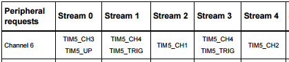
It lets us use all of TIM5’s 4 channels to capture both the step and dir signals, to be DMA’d into separate buffers of appropriate size.
I checked: the DMA controller supports separate streams for each capture channel on TIM5:
Other features of this pin shuffle:
- We get a 5th GPIO pin. This could be used for anything, but specifically it could be used as an Enable line, a feature @Giornoxx was requesting.
- We get 4 Analog capable GPIO pins. This enables the possibility of 2 channels worth of sin/cos encoders.
- We can use the GPIO pins for UART (we couldn’t before). We actually get 2 UART ports, not sure if that will ever be needed, but still. Getting the UART is actually great, because the only other way to talk to an mBed or Arduino or whatever before, was with the SPI. But that SPI is also used by the gate drivers, which makes it really messy.
- (con): We lose the V_AUX port. However I don’t think that’s too bad: in the case where the drive is set up with the “battery on bus, and power supply on AUX port”, the voltage of the power supply should be constant, and could just be configured by the user.
Let me know what you guys think, and I’ll make this shuffle happen for v3.3.
Ok, makes sense to move it to a new thread and collect everything at one position! 
I am a bit tight on time and haven’t received the board yet (hoped it would arrive today …) but my first step approach was simply to use one independent input capture interrupt per motor for the step-pin and attach a short (as short as possible) interrupt, like demonstrated here:
Due to the design of the input capture interrupts on the stm32f4 platform and the already defined gpios it has to be on two independent IRQ lines (means both step pins should not have the same port count number PXN, where N should be different)
Also I have not read the reference manual and the existing code thoroughly enough to say if it is a problem to use lines which are in use for the encoder interface.
In the long run something like DMA to get the position might be more efficient, but using interrupts is probably the quickest and easiest way to get started.
Given the clock speed of the processor and a reasonable step frequency (0.5MHz would be really fast actually, usual 3D printer boards are not going that high even with high microstepping) I don’t think there are any issues with doing it with interrupts.
Also the interrupt would be really simple if we can just alter the internal motor position variable (maybe with a variable prescaler) after polling the dir pin.
I think this should be only a handful of cycles and no issue on the performance should be expected.
Not sure whether overrun may be an issue here
This for sure only works in position mode and I have no idea if there is excessive jitter with this (also dependent on the frequency the control loop is working with) but it could be worth a try. A more sophisticated approach could try to estimate the current velocity to smooth the movements especially on low speeds.
I think that interrupts are going to be the right answer here, you don’t have any idea when the signals are going to arrive, and they need to be processed with as low a latency as is possible. That doesn’t seem like a good fit for a DMA process.
Just to avoid confusion: Input Capture is a feature of the TIM hardware modules to automatically timestamp the edge of an input digital signal. This can be wired up with the DMA to send the timestamps to a buffer without any interrupts or intervention by the CPU.
What you are talking about are the GPIO External Interrupts. They indeed are multiplexed in a way that all interrupts on the same pin number, across all the ports, map to the same interrupt flag, and handler. Also, in relation to your question about contention with the encoder lines: the encoder doesn’t use the GPIO External Interrupts, it uses the Encoder mode of TIM3 and TIM4, so there is no contention in that sense.
My suggestion would be to aim for the Input Capture and DMA option for v3.3 that has the pins available on TIM5. To ensure compatibility for v3.2, we can let TIM5 still be running as a timebase, and use the External Interrupts to timestamp the edges in software, and store to a similar buffer as in the DMA solution. Then the post processing of the timestamp buffers can be common.
Speaking of post processing, and in relation to your comment about jittter: My idea would be to run a PLL, similar to that of the encoder, to track filtered position and velocity.
I was under the impression that DMA has lower latencies than the CPU. If you check this application note, it would seem that the latency of the DMA is on the order of 5 clocks to complete the tansfer, which is way shorter than the interrupt latency. Not to mention, it doesn’t interrupt the execution on the CPU.
Yes, things are a bit different with this chip than with avr 
May need some time to get the used to the concepts …
I couldn’t get a clear number for interrupt latencies on the STM32, but I got one link suggesting it would be ~12 clock cycles (but not an official STM doc):
https://www.google.de/url?sa=t&rct=j&q=&esrc=s&source=web&cd=2&ved=0ahUKEwi1kInYyrXUAhUHL1AKHW8EAvwQFggvMAE&url=http%3A%2F%2Fwww.eng.auburn.edu%2F~nelson%2Fcourses%2Felec5260_6260%2Fslides%2FARM%20STM32F407%20Interrupts.pdf&usg=AFQjCNEIjcsjEWxSsK6e-cMxtSzRr45vjQ&sig2=PrTC-Ypm9nDaANQuqunEhA
Still think for a quick and dirty approach it may work well enough (12 cycles is still 14 times faster than a high 100khz step rate) but an optimised concept for sure will be preferred
Easiest way would be to have an external logic converting step/dir to quadrature signal 
What I’m currently trying to figure out is how it may work with the DMA at all as from my (very basic) understanding (and more linked to pc than microcontrollers) DMA is perfect for writing data in the background to memory which comes already in a streamed (but less timing sensitive) manner.
E.g. data from hard drive or network controller.
But as you mention it’s possible to get time stamps this approach may work well, I’ll continue reading the AN you mentioned to get a grip on it …
1 Like
Just checking in, How are we doing on the Step - Dir interface, Any ETA?
I think I can get started on it in about a week from now or so.