Little more info, when ERROR_DRV_FAULT occurs and the motor is de-enegised, the periodic spikes disappear.
I’ve got a v3.4 48volt version which looks a bit different, I’ll flash that tomorrow and retry.
Little more info, when ERROR_DRV_FAULT occurs and the motor is de-enegised, the periodic spikes disappear.
I’ve got a v3.4 48volt version which looks a bit different, I’ll flash that tomorrow and retry.
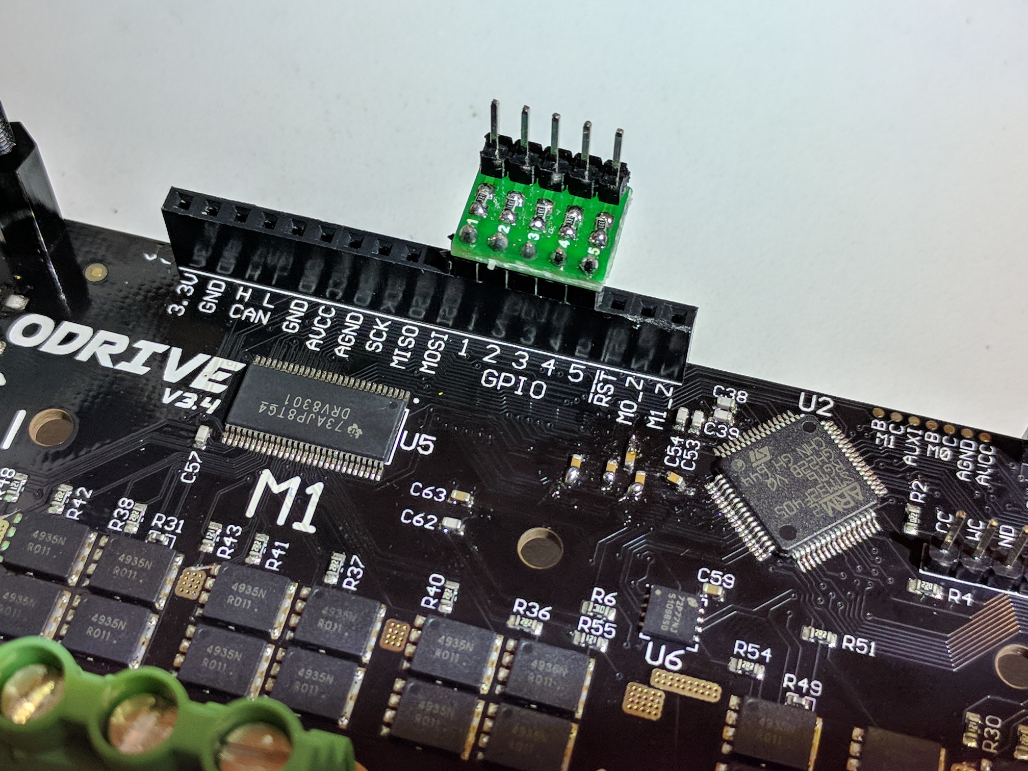
Yes it’s very easy to have noise couple into the step/dir signals. ODrive v3.5 has some RC filters on the inputs to help mitigate this. On v3.4 I had good results when soldering in some RC filters, though it was a bit fiddly to get the capacitors into place. I used 330 ohm and 4.7nF. Here are some pictures of what I did:
I had some passive breakout boards that made it really convenient to insert the series resistors. If you don’t have this, you can just use through hole resistors. You can also see where I soldered in the capacitors next to the ARM chip.
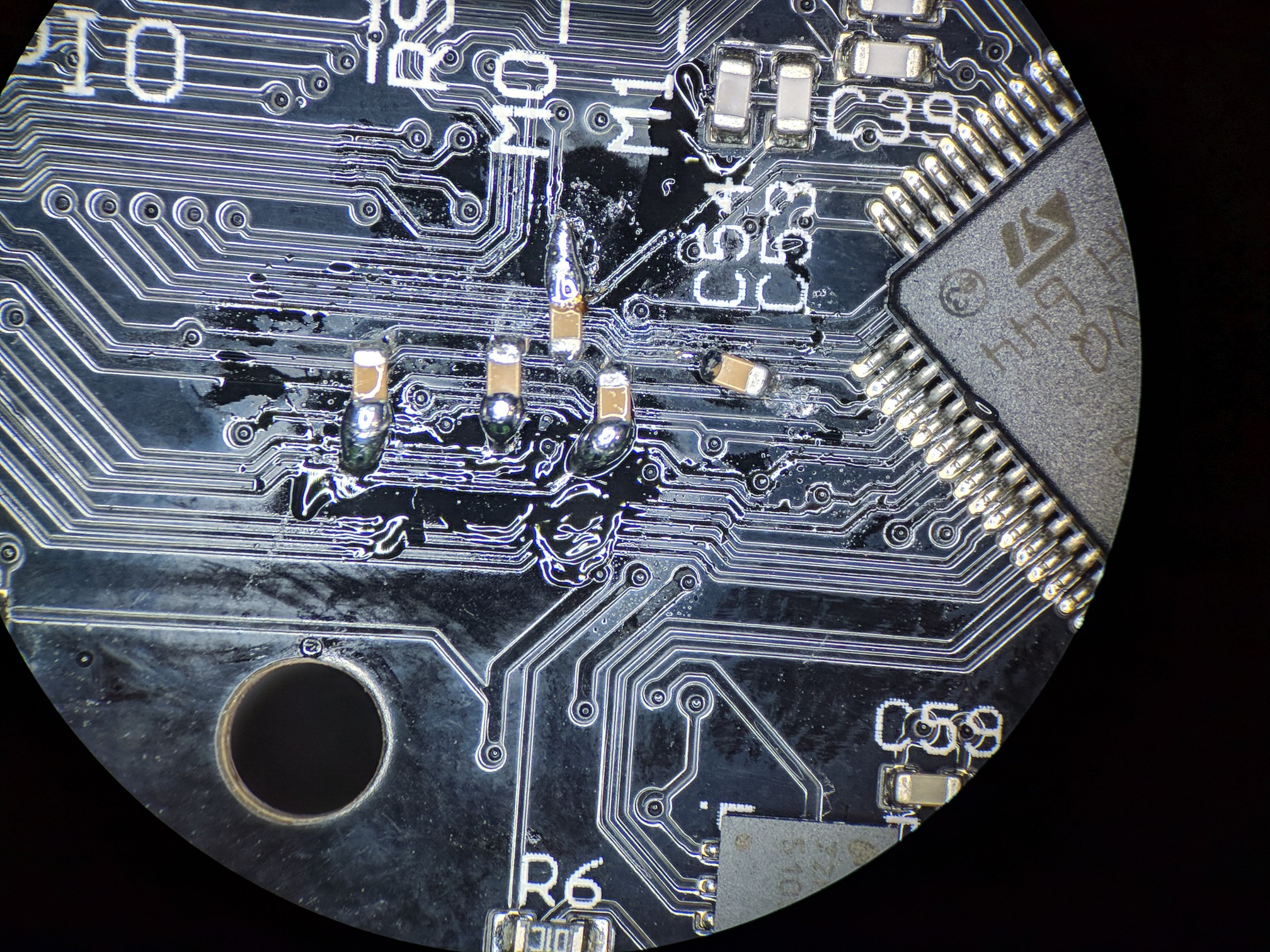
I decided that it was more convenient and likely to yeild the best results for me to put the capacitors as close to the ARM chip as possible, connected directly to the GND that feeds it. You can see the GND is the upper of the thick top (red) traces if you zoom in the picture.
I scraped off the solder mask and used long solder blobs to reach across to get connections I wanted.
If you think it is too fiddly for you to install the capacitors the way I did, you can try to have them be external right at the J3 connector.
Thank you Oskar for your quick reply and fix, I’ll implement that mod and report back. Cheers.
Excellent, That’s fixed it. Thank you Oskar.
I’m having problems with Step and Direction mode picking up extra steps. The Step input seems to be sensitive to interference. I’ve played around with different values on the RC network, but can’t eradicate it totally.
My ODrive is within 15cm of the motor which I think maybe the source, so I’m going to try extending the motor and encoder wires.
I was also wondering if a configurable software dead time to the Step input could be possible, to ignore pulses less than a certain width?
Extending the distance of the ODrive to the motor to just over a metre didnt help.
In the interrupt routine for the Step input, I was thinking of inserting a short delay, then checking the status of that input and if it was still high, then perform the step, otherwise dismiss it as a false input and return without doing anything. Can you see any problem with doing that?
I’ll chime in here, and I really don’t know about odrive, but I would hesitate ever solving a hardware issue with a software patch of sorts. Creating a check is fine unless you are doing it as a solution to ignore a constant unknown problem. My experience has been this method, while easier, has a high chance of compounding the problem at high speeds or in even noisier environments. Even the resources allocated to the check itself can become a problem down the road. Grounding, shielding and understanding component isolation are a better direction in this case. Software should only come after the hardware is solid or you risk redesign at a painfully late stage. My 2c.
I don’t want to insult you so ignore if you’re past this, but twisted wire pairs solves a lot of these issues and often gets overlooked. Good luck.
@Neil_FV Where did you add in the capacitors for the RC network? Was it soldered close to the STM like my example, or somewhere else?
I soldered them over the “4” of the “48V” silkscreen, probably too far from the processor I’m guessing.
The Odrive 3.5 is doing much better! I have implemented the Step/Dir and it seems to be pretty stable. I am not getting extra steps or missing any so I am pretty happy. The Odrive is getting much more mature. The Odrive Tool ROCKS! I am having a couple of problems tho. For one thing I can’t get the Index to work. I am using an AMT102 and I do have the X (on the encoder) hooked up to the Z pin. The next thing is that the motor will go into high velocity free running at random. I have run through a G code file and sometimes it will go fine and other times it will go into the free run. I have read in the troubleshooting guide " Motor cuts off or spins uncontrollably at high rotational speeds (ie: > 5000 RPM)" but the G code I am running is not approaching any where near 5000 rpm.
and the last thing is when in the Odrive Tool after rebooting I get this
ChannelBrokenException Traceback (most recent call last)
~\Anaconda3\lib\site-packages\fibre\shell.py in
----> 1 odrv0.reboot()
~\Anaconda3\lib\site-packages\fibre\remote_object.py in call(self, *args)
160 for i in range(len(args)):
161 self._inputs[i].set_value(args[i])
–> 162 self._parent.channel.remote_endpoint_operation(self._trigger_id, None, True, 0)
163 if len(self._outputs) > 0:
164 return self._outputs[0].get_value()
~\Anaconda3\lib\site-packages\fibre\protocol.py in remote_endpoint_operation(self, endpoint_id, input, expect_ack, outpu
t_length)
313 return self._responses.pop(seq_no)
314 # TODO: record channel statistics
–> 315 raise ChannelBrokenException() # Too many resend attempts
316 finally:
317 self._expected_acks.pop(seq_no)
ChannelBrokenException:"
I have gotten a lot further in a lot less time than the first time around. Thanks for all the hard work!
Hi @Bart,
Do you use the shielded cable we provide for the AMT102? Or something else?
The runnaway is usually caused by mechanical slip of the encoder, or noise on the wiring to the encoder due to improper shielding.
Does anyone know about the “ChannelBrokenException” I asked about above?
That exception is normal after rebooting the ODrive.
Hi everybody,
We are trying to move a heavy load with the odrive step/dir interface. When we arrive at the desired position we use mechanical brakes mounted on the BLDC motor rotor to secure the position (we don’t want to only rely on the closed loop control).
The problem is that if we force the rotor to a fixed position the error in the control loop is never zero, so the controller try to move the rotor and rise the current, and we don’t want that.
Do you think possible to modify the firmware to use a GPIO to act as an enable pin?
@jujuoik9 You could try to set the vel_integrator_gain to 0. (OdrvX.axisX.controller.config.vel_integrator_gain)
That is the gain that is responsible for the integral part of the PI control loop. In other words, the parameter that is responsible for increasing the current over time, even when position and velocity errors don’t change.
However, you will always have a current (high or low, depends) flowing when the error is not 0, but further tuning of the other gains may lower that current to an acceptable one. But be aware that when those parameters are not correctly tuned, the accuracy will degrade significantly.
I do also think it is possible to change the firmware to include an ‘enable’ pin.
hi @LowiekVDS, our problem is that the charge we apply on the rotor can vary so we need the integrator gain in order not to have a static error.
When i plot the integrator current, it never stop to fluctuate even when the error is null, do you think there is a way to stop the integrator action once we arrive at the setpoint?
Yeah, you can just set vel_integrator_gain = 0 when you apply the brakes, and set it back when you release the brakes. We also have “enable pin” on the roadmap but who knows when it’ll get written. Unless someone wants to help 
Hi,
As we cannot change the integrator gain (we only control the odrive via step/dir), our only solution is to implement the enable for the step/dir interface on the gpio5.
I would have implemented it by adding
void Axis::set_step_dir_active(bool active) {
    if (active) {
        if (!HAL_GPIO_ReadPin(enable_port_, enable_pin_)) this.requested_state_ = AXIS_STATE_IDLE; //if the enable pin isn't set we stop the control loop*
        ...
and add somewhere in the Axis::run_idle_loop
if (HAL_GPIO_ReadPin(enable_port_, enable_pin_) && config_.enable_step_dir) this.requested_state_ = AXIS_STATE_CLOSED_LOOP_CONTROL; //maybe there are others things to check before going back to closed loop control from the idle state...
But i think if it was that easy the feature would be already there. Does someone sees something missing ?
Ok so here’s what I did :
First I modified the AxisHardwareConfig_t structure in board_config_v3.h by adding an enable pin :
typedef struct {
    uint16_t step_gpio_pin;
    uint16_t dir_gpio_pin;
    uint16_t enable_gpio_pin;
    osPriority thread_priority;
} AxisHardwareConfig_t;
And set it to GPIO5 for M0 and GPIO6 for M1 :
//M0
.axis_config = {
    .step_gpio_pin = 1,
    .dir_gpio_pin = 2,
    .enable_gpio_pin = 5,
    .thread_priority = (osPriority)(osPriorityHigh + (osPriority)1),
},
…
//M1
.axis_config = {
#if HW_VERSION_MAJOR == 3 && HW_VERSION_MINOR >= 5
    .step_gpio_pin = 7,
    .dir_gpio_pin = 8,
    .enable_gpio_pin = 6,
I then modified the run_idle_loop() in axis.cpp (the debounce function is only here because I use a button to switch from enable/disable, eventually this will disapear) :
bool Axis::run_idle_loop() {
    // run_control_loop ignores missed modulation timing updates
    // if and only if we're in AXIS_STATE_IDLE
    safety_critical_disarm_motor_pwm(motor_);
    run_control_loop([this](){
        if (debounce_button(enable_port_, enable_pin_) && config_.enable_step_dir) requested_state_ = AXIS_STATE_CLOSED_LOOP_CONTROL;
        return true;
    });
    return check_for_errors();
}
and I did the opposit way in the Axis::run_closed_loop_control_loop() :
bool Axis::run_closed_loop_control_loop() {
// To avoid any transient on startup, we intialize the setpoint to be the current position
controller_.pos_setpoint_ = encoder_.pos_estimate_;
set_step_dir_active(config_.enable_step_dir);
run_control_loop([this](){
// Note that all estimators are updated in the loop prefix in run_control_loop
// Check the enable pin
if (!debounce_button(enable_port_, enable_pin_) && config_.enable_step_dir) requested_state_ = AXIS_STATE_IDLE;
float current_setpoint;
if (!controller_.update(encoder_.pos_estimate_, encoder_.vel_estimate_, ¤t_setpoint))
return error_ |= ERROR_CONTROLLER_FAILED, false; //TODO: Make controller.set_error
float phase_vel = 2*M_PI * encoder_.vel_estimate_ / (float)encoder_.config_.cpr * motor_.config_.pole_pairs;
if (!motor_.update(current_setpoint, encoder_.phase_, phase_vel))
return false; // set_error should update axis.error_
return true;
});
set_step_dir_active(false);
return check_for_errors();
}
For now it seems to work well, I’ll keep you updated