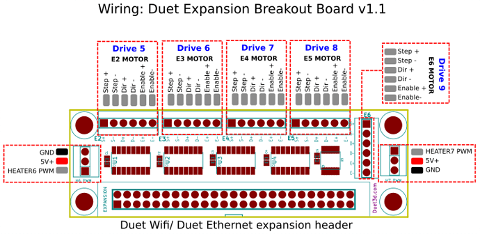
Step / Direction

@jujuoik9 You could try to set the vel_integrator_gain to 0. (OdrvX.axisX.controller.config.vel_integrator_gain)

That is the gain that is responsible for the integral part of the PI control loop. In other words, the parameter that is responsible for increasing the current over time, even when position and velocity errors don’t change.

However, you will always have a current (high or low, depends) flowing when the error is not 0, but further tuning of the other gains may lower that current to an acceptable one. But be aware that when those parameters are not correctly tuned, the accuracy will degrade significantly.

I do also think it is possible to change the firmware to include an ‘enable’ pin.

2 Likes

hi @LowiekVDS, our problem is that the charge we apply on the rotor can vary so we need the integrator gain in order not to have a static error.

When i plot the integrator current, it never stop to fluctuate even when the error is null, do you think there is a way to stop the integrator action once we arrive at the setpoint?

Yeah, you can just set vel_integrator_gain = 0 when you apply the brakes, and set it back when you release the brakes. We also have “enable pin” on the roadmap but who knows when it’ll get written. Unless someone wants to help :smiley:

1 Like

Hi,

As we cannot change the integrator gain (we only control the odrive via step/dir), our only solution is to implement the enable for the step/dir interface on the gpio5.

I would have implemented it by adding

void Axis::set_step_dir_active(bool active) {
    if (active) {
        if (!HAL_GPIO_ReadPin(enable_port_, enable_pin_)) this.requested_state_ = AXIS_STATE_IDLE; //if the enable pin isn't set we stop the control loop*
        ...

and add somewhere in the Axis::run_idle_loop

if (HAL_GPIO_ReadPin(enable_port_, enable_pin_) && config_.enable_step_dir) this.requested_state_ = AXIS_STATE_CLOSED_LOOP_CONTROL; //maybe there are others things to check before going back to closed loop control from the idle state...

But i think if it was that easy the feature would be already there. Does someone sees something missing ?

Ok so here’s what I did :

First I modified the AxisHardwareConfig_t structure in board_config_v3.h by adding an enable pin :

typedef struct {
    uint16_t step_gpio_pin;
    uint16_t dir_gpio_pin;
    uint16_t enable_gpio_pin;
    osPriority thread_priority;
} AxisHardwareConfig_t;

And set it to GPIO5 for M0 and GPIO6 for M1 :

//M0
.axis_config = {
    .step_gpio_pin = 1,
    .dir_gpio_pin = 2,
    .enable_gpio_pin = 5,
    .thread_priority = (osPriority)(osPriorityHigh + (osPriority)1),
},

//M1
.axis_config = {
#if HW_VERSION_MAJOR == 3 && HW_VERSION_MINOR >= 5
    .step_gpio_pin = 7,
    .dir_gpio_pin = 8,
    .enable_gpio_pin = 6,

I then modified the run_idle_loop() in axis.cpp (the debounce function is only here because I use a button to switch from enable/disable, eventually this will disapear) :

bool Axis::run_idle_loop() {
    // run_control_loop ignores missed modulation timing updates
    // if and only if we're in AXIS_STATE_IDLE
    safety_critical_disarm_motor_pwm(motor_);
    run_control_loop([this](){
        if (debounce_button(enable_port_, enable_pin_) && config_.enable_step_dir) requested_state_ = AXIS_STATE_CLOSED_LOOP_CONTROL;
        return true;
    });
    return check_for_errors();
}

and I did the opposit way in the Axis::run_closed_loop_control_loop() :

bool Axis::run_closed_loop_control_loop() {
    // To avoid any transient on startup, we intialize the setpoint to be the current position
    controller_.pos_setpoint_ = encoder_.pos_estimate_;
    set_step_dir_active(config_.enable_step_dir);
    run_control_loop([this](){
        // Note that all estimators are updated in the loop prefix in run_control_loop
        // Check the enable pin
        if (!debounce_button(enable_port_, enable_pin_) && config_.enable_step_dir) requested_state_ = AXIS_STATE_IDLE;
        float current_setpoint;
        if (!controller_.update(encoder_.pos_estimate_, encoder_.vel_estimate_, &current_setpoint))
            return error_ |= ERROR_CONTROLLER_FAILED, false; //TODO: Make controller.set_error
        float phase_vel = 2*M_PI * encoder_.vel_estimate_ / (float)encoder_.config_.cpr * motor_.config_.pole_pairs;
        if (!motor_.update(current_setpoint, encoder_.phase_, phase_vel))
            return false; // set_error should update axis.error_
        return true;
    });
    set_step_dir_active(false);
    return check_for_errors();
}

For now it seems to work well, I’ll keep you updated :slight_smile:

1 Like

How to connect “step -” and “step +” pins on ODrive? As on ODrive there is only Step pin.