Hey Oskar, it seems from the second demo posted on the site that both motors move together in a coordinated way. Do you achieve this by sequentially issuing independent commands for both motors through USB, assuming that the delay is tiny?
From the source code the command is parsed by motor_parse_cmd() when received over USB, it sets the parameters of global data structure motors[]. Then I’m assuming motor threads read those parameters and execute motor motion
Would it be possible to synchronize both motors by having another command that sets parameters for both motors simultaneously?
This is the code that handles the position commands:
if (buffer[0] == 'p') {
// position control
int motor_number;
float pos_setpoint, vel_feed_forward, current_feed_forward;
int numscan =
sscanf((const char *)buffer, "p %u %f %f %f", &motor_number,
&pos_setpoint, &vel_feed_forward, ¤t_feed_forward);
if (numscan == 4 && motor_number < Motor::getNumMotors()) {
Controller::set_pos_setpoint(*Motor::getMotorByID(motor_number), pos_setpoint, vel_feed_forward, current_feed_forward);
}
}
The easiest way to have this handle both motors in one command is to create a NEW command that accepts values for both motors simultaneously. Alternatively, give it an X/Y coordinate and have some mapping from X and Y to motor0 and motor1. However, this won’t necessarily result in coordinated motion.
The “real” way to synchronize the motors is to plot a trajectory from the current position to the new position, then execute that. It’s something I want to do but I don’t have time for right now.
It would be great if there was a way to include a virtual axis in the control, to which real axis’ are synchronized, as is the case in real world motion controllers, but this would likely need to be a separate controller to provide this functionality.
So the correct way to do this is to use a trajectory generator and follower, as mentioned by @Wetmelon. This is a planned feature with quite high priority, as seen here.
The pen plotting demo did indeed use a coordinated trajectory tracker, but that was from an old code-base which won’t work directly here, and we want to improve it anyway.
Until the trajectory generator is completed, you can indeed send position commands to both M0 followed by M1, back-to-back. You will not get straight-line movement, nor any information about when the move is done; but the machine will go to the location you specified via some arbitrary path and by some arbitrary time.
To answer @JTRACKER’s question: The trajectory generator/follower sits separately from the individual motor controllers, and we would only want one of them to coordinated between multiple axis. So in the first instance we would make a single generator/tracker on the ODrive guiding the 2 axes.
However, there is no particular reason why we would be restricted to coordinating between two axes only, we could make it plot n-dimensional trajectories. We would then need to broadcast the trajectory parameters and trigger signals to other axes, to be tracked locally; or we track all axes on one board and stream realtime position set-points at a high rate.
1 Like
So for my application of coordinating 6 O-drive axis, how would you suggest the application would be developed to run a Stewart platform? 
1 Like
ODrive Stewart platform sounds very badass! Is this for a person to ride on, like a simulator? ;D
I think the trajectory generator/follower is the way to go for pre-defined moves. Another way to do it is to have your host (say simulation software if that’s your application) stream position and velocity set-points to all the drives at some high rate, 100Hz - 200Hz or so.
Check this out ![]()
I’m going to be driving some linear actuators with your hardware, in lieu of large 3-phase motors or commercial servo motors. There are some quite costly BLDC actuators available, but will be fabricating the actuators myself.
I’ve been working on this project for years, but your project along with Thanos (look him up if you’re interested), Ian (@BFF) and Douwe (glider sim) have provided a ton of resources. These guys have provided significant direction and support to the DIY Flight Sim network.
https://www.kickstarter.com/projects/1096461972/6dof-electronic-interface-for-motion-simulator-pla/

I’ve worked on Flight Simulators while in the Air Force and spent 15 years in the industrial automation world while employed at Bosch. I love to bring my work home ![]()
Thanks for the continued effort on this awesome new product.
1 Like
Woah awesome!! Thanks for choosing to pioneer this with ODrive!
The motion controller that’s on that kickstarter should be compatible with ODrive through the PWM interface on ODrive v3.3 and newer.
The firmware for PWM input isn’t ready yet, but it should be quite easy to add; and we have the hardware timers (TIM5) on the GPIO pins ready for that on v3.3.
1 Like
I only have 3 of the ODrive v3.2, so I will need to figure something out. Just getting into the details.
The motion controller has a servo interface option which provides +/- 10V command outputs to the drive.
Hi Jtracker, are you still going ahead with the 6 dof build???
please let us know!
As it stands, the project is shelved and have gone direct to a full servo (motor/drive) application.
1 Like
Hi Jtracker, I’ve been looking at a 4/6 DOF system using AMC1280USB, but having some trouble finding compatible servo/drivers to match the 1280 board.
Is it possible to share a little your experience building your rig?
And can you say what software (Sim commander/ X-Sim) you are using?
Regards Jerry
Hi Jerry,
I’m not sure how this discussion should proceed as it is no longer an ODrive conversation and should likely take it offline.
Message me and I will see what we can discuss further.
JT
Well, can I synchronize serval odrive at same time? I have to use up to odrive in my project.
I don’t understand why a trajectory generator and follower is the right way to do this…
1.) It would seem like a lot more processing and bandwidth for the follower to track the leader compared to having every motor plan a linear move and only make adjustments if one or more motors are inaccurate.
Stated another way, it seems likely that a follower will be hunting around to track the lead motors position… Trying to catch up and go faster at a point when the lead is overspeed and trying to slow down for example. Wouldn’t you end up with a better result if you ran both motors with a profile so they both hunted to a stable target speed/position?
2.) How would a follower system handle the case when a following motor lags?
Madcowswe - Can you share any more about the old code-base that did this, and the ideas you have on how to implement the new version?
Thanks
Daniel
I think you misunderstand, that is what a trajectory follower is doing. Generator/follower doesn’t mean one motor is tracking a different motor, it means we generate a mathematical trajectory, and they all follow it over time.
Thanks… That makes sense.
What is involved in keeping a number of pid controlled servo motors in sync when one motor lags the others?
I was thinking of just writing some code to break up a move into segments and delay setting the next segment’s pid target until the slowest servo completes the current segment. However, that seems like it might create some noticable artifacts.
Is it important to also consider a situation where one servo leads rather than lags?
Thanks
Daniel
The classic approach is to put enough margin into the trajectory such that it is feasable for all axes to catch up if the fall a little behind. Then it is up to each axis individually to track (or get back on track). That is, it is not common to delay the trajectory if some axis isn’t keeping up. One important reason why it’s not easy to make a wait like this is if you consider the decelleration part of the trajectory: if one axis can’t slow down fast enough, slowing the trajectory down doesn’t help.
The common approach is simply to proceed with the trajectory blindly, and let each axis track as best they can. Then you can add an “emergency” tracking fault, that halts the whole machine and puts it into an error state if some axis tracks way too poorly.
The paper I’ve been following to create the trajectory planner talks about synchronization of multiple motors. They test it with a 7 axis robot arm. They generate 7 trajectories, figure out the slowest axis, then adjust the deceleration phase of all the other axes such that the total time is equal for all axes. Ends up looking like this:
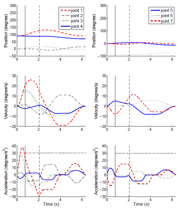
Note that all the joints reach 0 velocity simultaneously. This is something that I want to add once we have the Jerk-limited algorithm integrated.