Hello,
I am working on firmware modification to allow running time parameterized trajectory points generated by fitting a cubic spline, which is generated by ROS Moveit software (which deals with robotic manipulators in ROS).
(link to branch on my fork)
The motivations are:
- a joint of the robotic arm have to be at a certain position synchronously with other joints for the pose to make sense. For example moving the arm while having the end effector parallel to the floor.
- sending fine-grain setpoints takes up communication bandwidth (I am using a CAN bus), and is difficult to synchronize accross multiple Axes.
Because the trapezoidal trajectory control is already implemented, I used the same pattern:
- save the starting time, plug in current time to a equation in each control loop to get pos_setpoint and vel_setpoint.
- The difference is that there is a buffer to hold multiple trajectory points which has its own cubic function for position and quadratic function for velocity. (new points are loaded as time progresses)
- synchronizing (start signal) will be done by a high priority CAN message meant for all ODrive nodes.
- the control ends when there is no next point in the buffer, switching to CTRL_MODE_POSITION_CONTROL
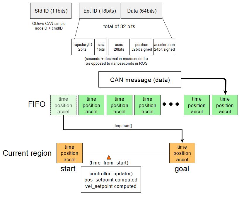
Here is a diagram of the implementation:
FIFO and ‘current region’ in the picture are queues implemented as linked list.
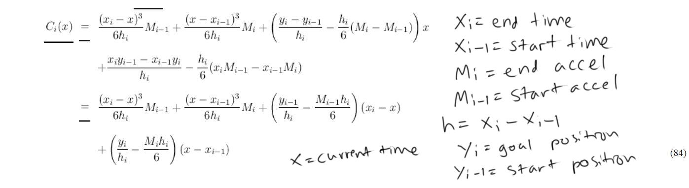
The equation used to make cubic polynomial (to compute pos_setpoint) from position, acceleration, and time of two points (from a spline) (velocity function used is just the derivative of this equation). (courtesy of Ruye Wang hmc.edu):
I used trajectory points generated from ROS moveit package which looks like following when the above equations are computed using python: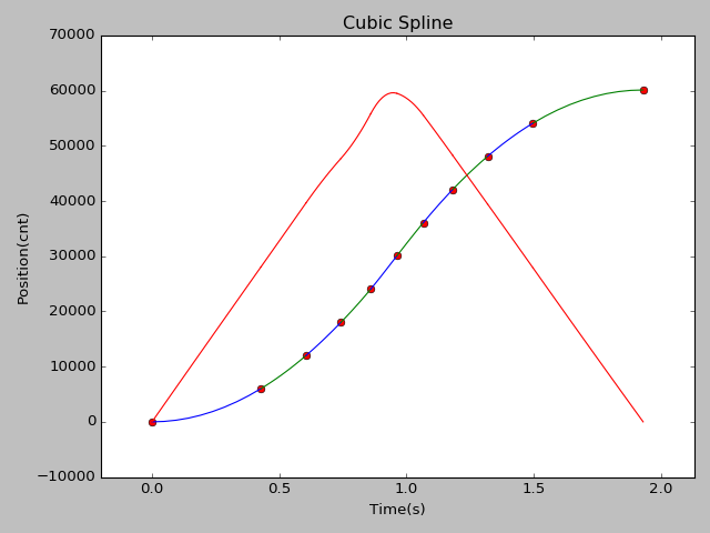
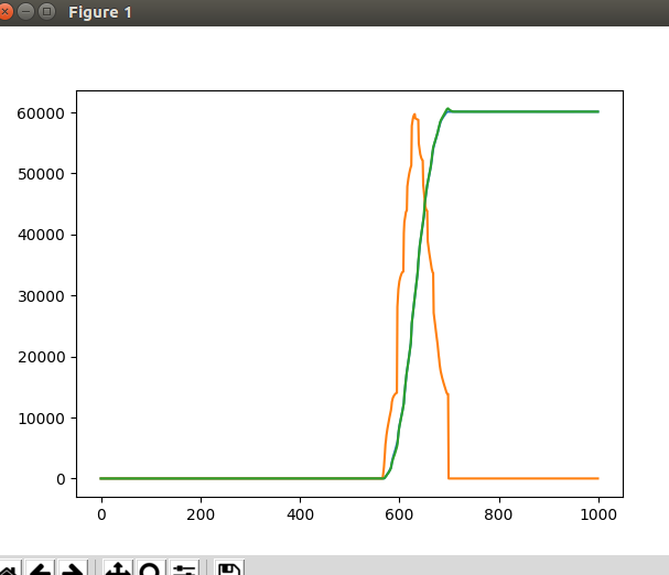
and here is a capture from ODrive liveplotter on hardware:
orange = vel_setpoint, green = pos_estimate
As you can see from the liveplotter output, it is not quite working right.
- The vel_setpoint seems to be lagging behind a bit and eventually causes an overshoot (seems small in the plot but its almost 1/8 turn of the motor).
- I have measured the time required to compute pos_setpoint and vel_setpoint with an oscilloscope to be 3 microseconds.
Is it taking up too much time in the control loop? Maybe the approach is just wrong? I appologize if the code is hard to read
(controller update)
(computing pos_setpoint, vel_setpoint)
I am kind of stuck and ask for some suggestion. Thanks.
Looks like you have some sort of osciallation in the velocity control, which is a bit odd. Also, are you sure you’re not saturating the current control in the motor? That could be what’s causing the overshoot.
EDIT: Side note, have you had any issues with the CAN communication? If it’s working well for you too, then I think we have enough people for whom it works well that we can merge it into develop.
Thanks for the suggestion. I do have motor.config.current_lim a bit higher than rated current but I will try bumping up more. I haven’t thought about the current loop affecting the velocity set_point. I did decrease the vel_gain a bit too maybe that has an effect.
I am confused because pos_setpoint looks as expected while velocity is not and they are using the same timing.
As with CAN communication, I have been using it quite a bit (6 ODrive nodes, 1 non-ODrive node) and I didn’t have any problem at all. Very stable. (I haven’t tested every command tho)
I just wonder if node_id can be used in hardware filter so that handle_can_message is not invoked for unrelated messages. Also I did modify get_node_id and get_cmd_id to handle CAN_extended messages:
uint8_t CANSimple::get_node_id(uint32_t msgID) {
    if (msgID > 0x7ff) {
        return ((msgID >> (NUM_CAN_EXT_ID_BITS + NUM_CMD_ID_BITS)) & 0x03F);
    }
    return ((msgID >> NUM_CMD_ID_BITS) & 0x03F);  // Upper 6 bits
}

uint8_t CANSimple::get_cmd_id(uint32_t msgID) {
    if (msgID > 0x7ff) {
        return ((msgID >> NUM_CAN_EXT_ID_BITS) & 0x03F);
    }
    return (msgID & 0x01F);  // Bottom 5 bits
}
Is there a code formatter for the project? my vscode changes whitespaces causing unnecessary changes to the files.
If you open the ODrive Workspace, you’ll get the settings:
"C_Cpp.clang_format_style": "{ BasedOnStyle: Google, IndentWidth: 4, ColumnLimit: 0 }",
Then right-click & format will format it according to those rules. We don’t have the .clang-format in the folder yet.
@Wetmelon thanks, I was asking in case of any PR in the future.
So I figured it out and it turned out to be a mistake in the formula for calculating vel_setpoint. I wrote it down wrong on paper when copying from python and I was double checking cpp code against this paper!
now it looks correct and overshoot is gone: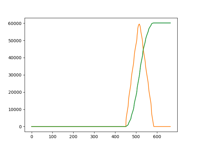
2 Likes
Dear Sir,
the paper you mentioned for calculating vel_setpoint can’t be found any more.
Could you help me to confirm whether the following formula is correct?
    // float x1 = pow((tf - t),3)*ai/(6*h) + pow((t-ti),3)*af/(6*h)+(xi/h-ai*h/6)*(ti-t)+(xf/h-af*h/6)*(t-ti);
    // float dx1 = -pow((tf - t),2)*ai/(2*h) + pow((t-ti),2)/(2*h) + (xf-xi)/h - (af-ai)*h/6;
Thanks in advance