Trapezoidal Trajectory Planner

Hello everyone,

Over the last few weeks I’ve been working on implementing a trajectory planner for use with ODrive, and I’m excited to say that stage one - Trapezoidal (acceleration limited) trajectories - is ready for testing. There is a pull request for it here https://github.com/madcowswe/ODrive/pull/210, and you can pull the branch directly here https://github.com/Wetmelon/ODrive/tree/TrajPlan.

Results

Results first! Everyone loves graphs, and thanks to @Richard_Parsons we were able to get graphs from real-time testing (not just Python simulations). Richard used his flywheel setup to create a challenging high-inertia system for ODrive.

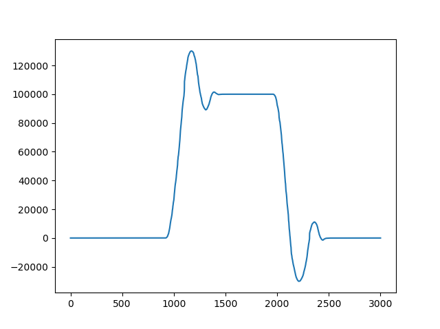
Unplanned move with high gains:
image

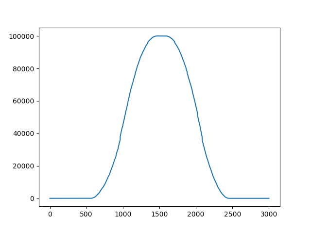
Same gains, with planner
image

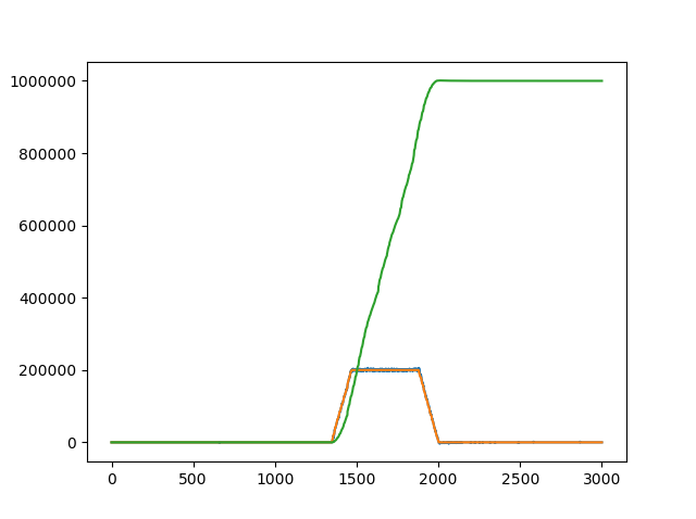
Long distance move after tuning:
image

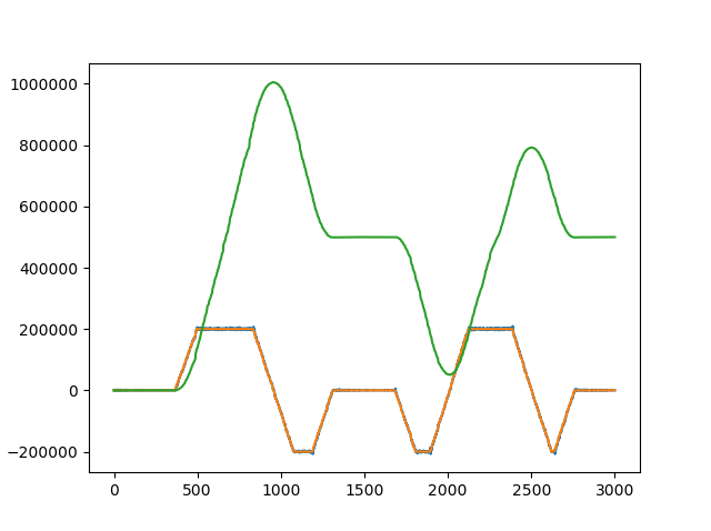
Calling move_to_pos in the middle of a move:
image

Using The Planner

To use it, you need to first setup your trajectory planner limits (in encoder counts):

<odrv>.<axis>.trap_traj.config.vel_limit = <Float>
<odrv>.<axis>.trap_traj.config.accel_limit= <Float>
<odrv>.<axis>.trap_traj.config.decel_limit = <Float>

Note: You may want to set your controller.vel_limit slightly higher than your planned move velocity limit, to act as a safety without getting in the way.

Then, you can simply make function calls to move_to_pos() as follows:
<odrv>.<axis>.controller.move_to_pos(<Float>)

The move_to_pos command takes a position in encoder counts, computes a trajectory, and then switches the ODrive controller into CTRL_MODE_PLANNED_MOVE_CONTROL (4). In this mode, ODrive computes a new position and velocity setpoint during every update cycle. Current setpoint will also be used in the future when we have a good way to convert from acceleration to current/torque. When the move is complete, pos_setpoint is set to the final position, and vel_setpoint is set to 0. The controller then returns to CTRL_MODE_POSITION_CONTROL to maintain position.

Changes to the trajectory kinematic limits can be made during a move without breaking the planner, but move_to_pos must be called immediately after to recompute the trajectory.

Algorithm

The algorithm itself is an implementation of this paper (PDF Warning), which goes on to describe a fast time-optimal jerk-limited planner (which we plan to finish in the future). The implementation was first tested thoroughly in Python to ensure that all corner cases were handled gracefully, including short moves, overshoots, and mid-move kinematic limit changes . The C++ code came directly from the Python, with slight modifications to improve real-time behaviour. The python code is included under the “Tools” folder in the ODrive repository.

The algorithm is very fast, robust, and can be expanded to multi-axis synchronization by computing all trajectories in time-optimal mode, then using the slowest time and recomputing the trajectories in fixed-time mode. They demonstrate this with a 6 axis robot

7 Likes

I can’t stress enough just how big a difference this trajectory planner makes to the usefulness of odrive. It allows you to set very high PID gains so that the motor behaves like a stepper motor in terms of having a high stiffness when holding position while also allowing you to make rapid moves without overshooting your target position. I’m sure this feature will be very useful for almost everyone in the odrive community.

Great work @Wetmelon and I’m looking forward to trying out your multaxis planer when that ready :grinning:

Oh and for anyone wanting to learn more about trajectory planners I found this course to be quite informative.

4 Likes

A post was merged into an existing topic: How to use github?

Super curious about that flywheel, Richard… Is it part of some project?

The flywheel is for no specific project. Its just something I had on hand and so I thought it could be useful to for testing with the trajectory generator among other things. If you were ever wanting to make your own you could making a motor adaptor for one of these weights provided you kept the RPM low for dynamic balancing reasons.

If your curious, my flywheel came out of a machine a bit like this that was being thrown out at my place of work and so it was as easy as printing an adaptor for the motor in order to get up and running.

I understand you’re working off the jerk-constrained trajectory generation paper and I’m getting more accustomed to the code as it sits now. But purely out of curiosity, what would be the down- (and/or up-)side of generating a trajectory of positions over time based on the desired acceleration and velocity parameters and letting the positional PID do the work? It seems this would allow strong PIDs to be used for both move accuracy (as it “chases” the generated positions) and strong holding.

I think this is exactly what we do with the trajectory control mode.

I’ve spent some time cleaning up and enhancing @Wetmelon’s original implementation. If anyone is interested to test it out, it’s available here:

Please let us know if everything works, or if there are some issues.
Thanks

@madcowswe - Hmmm, I think i see it now. Y is the new position returned on each call to evalTrapTraj.

I was thrown off by the Yd and Ydd terms seemingly sending velocity and acceleration terms back. I guess I was just thinking of it more simply as a series of moves to a series of (potentially) arbitrary positions, letting the normal position-seeking logic deal with chasing down each “point”.

So what is the logic of sending the Yd and Ydd terms back and setting both vel_setpoint and current_setpoint?
Is it just an ODrive controller convention?

(And, man, does the English language fail us here - “current” as in “present time” and “current” as in “Amperage” - argh)

Yes so Yd and Ydd are the first and second derivatives of the trajectory at the present timestep. We do assist the controller from falling behind the trajectory using these; we pass the values as feed-forward to the controller. This means that the feedback (what you called PID (it’s not exactly PID, it’s close though)) only has to work to correct disturbances and unmodelled dynamics.

FYI: in this context, current_setpoint refers to electrical current (which produces torque, and hence proportional to the acceleration).

EDIT: Here is a diagram to help illustrate what we are doing:

The Source seems to be an interesting read on the subject. (note our implementation is not exactly like this, but the concept of the feed forward based on the trajectory is similar).

Just so everyone is aware, the Trajectory Planner module for trapezoidal trajectories is now available in FW 4.6.

Parameters

To use it, you have a whole new module and four new configuration values:

<odrv>.<axis>.trap_traj.config.vel_limit = <Float>
<odrv>.<axis>.trap_traj.config.accel_limit = <Float>
<odrv>.<axis>.trap_traj.config.decel_limit = <Float>
<odrv>.<axis>.trap_traj.config.A_per_css = <Float>

vel_limit is the maximum planned trajectory speed. This sets your coasting speed.
accel_limit is the maximum acceleration in counts / sec^2
decel_limit is the maximum deceleration in counts / sec^2
A_per_css is a value which correlates acceleration (in counts / sec^2) and motor current. It is 0 by default, and is not strictly necessary, but can improve response of your system if correctly tuned. Keep in mind this will need to change with the load / mass of your system.

All values should be strictly positive (>= 0).

Keep in mind that you must still set your safety limits as before. I recommend you set these a little higher ( > 10%) than the planner values, to give the PID controller enough control authority.

<odrv>.<axis>.motor.config.current_lim = <Float>
<odrv>.<axis>.controller.config.vel_limit = <Float>

Functions

Use the move_to_pos function to move to an absolute position:

<odrv>.<axis>.controller.move_to_pos(<Float>)

move_incremental is not yet implemented.
ramp_to_vel is not yet implemented.

2 Likes

These commands, are they available via UART Ascii protocol? Binary protocol?
My next step would be to send the commands from the CableCam Controller.

Second question is about motor slip. The CableCam has an additional Hall-Sensor on one of the two running wheels. Hence the motor position and the cablecam position have different scaling. But more important, the motor might slip a bit when accelerating or braking. Any idea how to merge the running wheel position into the position calculation?

The commands are available on the ASCII protocol.

t <axis> <position>

I don’t currently have a good answer for you re the 2nd encoder. This is something that’s done in other industries too (high precision PnP for instance), but we don’t support it yet.

beautiful! cant wait to try it!

I finally managed to test the trajectory planning on a serious setup (rather heavy corexy design where both motors are used)

For starters , can someone explain how to tune A_per_css ? I left default value and this might partly explain what’s below

Tested on odrive 3.5 48v with FW 0.4.8
The basic concept is that I use absolute encoder positions as targets. I then scale down vel_limit / accel_limit / decel_limit of the motor that has less counts to travel so that both motors finish moving at the same time; and thus make the head move in straight line moves.

I basically issue mov_to_pos commands (one per motor). Then I regularly poll for encoder counts to check that they are close enough to the target

I am facing weird behaviors such as

  • Two motors are not in sync (typically the head will not move in straight line). I have seen this in particular for some combination of moves from point B to A, but not point A to B ?!?
  • Experienced error 0x40
  • Sometimes, after a command was correctly execuyed by both motors, one motor would start moving alone slowly ! (As if it had received a command I did not issue !?)
  • All of the sudden during the execution both motors would make scary moves (sudden high acceleration and high speed) instead of executing expected behavior

It’s a bit hard to describe without video and I cannot entirely reproduce those behavior at will.

For now I stick to using my own planner but I would rather use the built-in one :confused:

Curious… very curious.

Please run the liveplotter while testing, with:

  • Target
  • Position, Velocity estimates

For one motor to start. The graphs tell us a lot about what the planner is trying to do.

I didn’t know you could use another software connection to the same odrive.
I poll for encoder estimates and motor errors every xx milliseconds. Can’t that polling and liveplotting interfere each other?

Can I have some guidance about tuning the a_per_css parameter? The manual claims that it should be tuned when mass/load is involved, which is the case here.

As a side note, I stumbled upon a cnc-made steel fly wheel that l intend to reuse to test the trajectory planner outside my corexy build

A_per_css is just inertia. Amps per count/s^2. So if you apply 1amp, how many counts / second^2 does the motor accelerate at? Or rather, the inverse.

I’m confused.

So in order to correctly configure it, I should somehow apply a 1A duty cycle, make a slowmo video to accurately measure the time it took to travel say 50cm, then assume the acceleration is somehow linear, deduct a counts/second^2, then inverse the value, and bingo: i have the right A_per_css ?

Would you have a better procedure ?

Yeah, pretty much. You don’t have to use 1A though, you can use whatever.

Or you can calculate it from the load and F = ma

Here’s a video on it https://youtu.be/wP9b-4Pl__8

A_per_css is worded that way because of how the trapezoidal planner works. It calculates the desired acceleration, velocity, and position for the whole trajectory in terms of counts. So:

Pos = counts
Vel = counts / second
Accel = counts / second^2

The position goes into pos_setpoint. The calculated velocity goes into vel_feedforward, but the acceleration must first be converted to current in Amps before it can be used for feedforward. Multiplying counts/sec^2 * A/(counts/sec^2) gives a result in Amps, which is fed into the motor control as Current_feedforward

1 Like