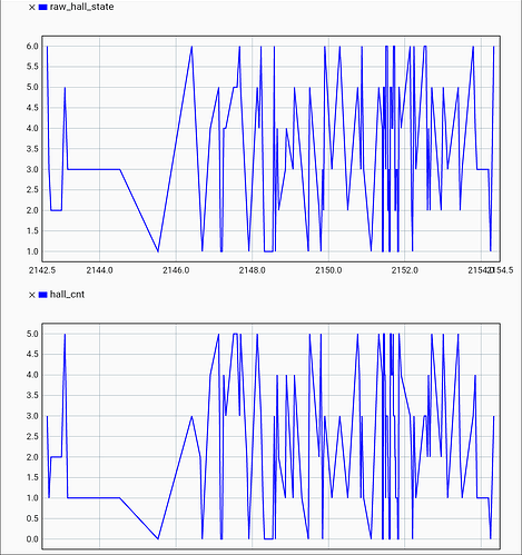
Thanks! Here is my config. I unfourtunately cant upload json files, so i had to attach the whole file as raw text:
{
  "can.config.baud_rate": 1000000,
  "can.config.data_baud_rate": 10000000,
  "can.config.tx_brs": 0,
  "can.config.protocol": 1,
  "config.enable_uart_a": false,
  "config.uart_a_baudrate": 115200,
  "config.usb_cdc_protocol": 3,
  "config.uart0_protocol": 3,
  "config.max_regen_current": 0.0,
  "config.dc_bus_undervoltage_trip_level": 10.5,
  "config.dc_bus_overvoltage_trip_level": 50.0,
  "config.dc_max_positive_current": 10.0,
  "config.dc_max_negative_current": -0.009999999776482582,
  "config.user_config_0": 0,
  "config.user_config_1": 0,
  "config.user_config_2": 0,
  "config.user_config_3": 0,
  "config.user_config_4": 0,
  "config.user_config_5": 0,
  "config.user_config_6": 0,
  "config.user_config_7": 0,
  "config.gpio0_mode": 17,
  "config.gpio1_mode": 17,
  "config.gpio2_mode": 17,
  "config.gpio3_mode": 17,
  "config.gpio4_mode": 17,
  "config.gpio5_mode": 17,
  "config.gpio6_mode": 17,
  "config.gpio7_mode": 17,
  "config.gpio8_mode": 17,
  "config.gpio9_mode": 17,
  "config.gpio10_mode": 17,
  "config.gpio11_mode": 17,
  "config.gpio12_mode": 17,
  "config.gpio8_pwm_mapping.endpoint": null,
  "config.gpio8_pwm_mapping.min": 0.0,
  "config.gpio8_pwm_mapping.max": 0.0,
  "config.gpio1_analog_mapping.endpoint": null,
  "config.gpio1_analog_mapping.min": 0.0,
  "config.gpio1_analog_mapping.max": 0.0,
  "config.gpio11_analog_mapping.endpoint": null,
  "config.gpio11_analog_mapping.min": 0.0,
  "config.gpio11_analog_mapping.max": 0.0,
  "config.brake_resistor0.enable": true,
  "config.brake_resistor0.resistance": 2.0,
  "config.brake_resistor0.enable_dc_bus_voltage_feedback": false,
  "config.brake_resistor0.dc_bus_voltage_feedback_ramp_start": 51.0,
  "config.brake_resistor0.dc_bus_voltage_feedback_ramp_end": 53.0,
  "config.inverter0.current_soft_max": 80.0,
  "config.inverter0.current_hard_max": 96.0,
  "config.inverter0.temp_limit_lower": 83.95999908447266,
  "config.inverter0.temp_limit_upper": 103.11000061035156,
  "config.inverter0.mod_magn_max": 0.6781481504440308,
  "config.inverter0.shunt_conductance": 1999.9998779296875,
  "config.inverter0.drv_config": 9029553697166464,
  "axis0.config.startup_max_wait_for_ready": 3.0,
  "axis0.config.startup_motor_calibration": false,
  "axis0.config.startup_encoder_index_search": false,
  "axis0.config.startup_encoder_offset_calibration": false,
  "axis0.config.startup_closed_loop_control": false,
  "axis0.config.startup_homing": false,
  "axis0.config.init_torque": 0.0,
  "axis0.config.init_vel": 0.0,
  "axis0.config.init_pos": NaN,
  "axis0.config.enable_step_dir": false,
  "axis0.config.step_dir_always_on": false,
  "axis0.config.calib_range": 0.019999999552965164,
  "axis0.config.calib_scan_distance": 8.0,
  "axis0.config.calib_scan_vel": 2.0,
  "axis0.config.index_search_at_target_vel_only": false,
  "axis0.config.watchdog_timeout": 0.0,
  "axis0.config.enable_watchdog": false,
  "axis0.config.step_gpio_pin": 8,
  "axis0.config.dir_gpio_pin": 5,
  "axis0.config.error_gpio_pin": 6,
  "axis0.config.enable_error_gpio": false,
  "axis0.config.calibration_lockin.current": 7.800000190734863,
  "axis0.config.calibration_lockin.ramp_time": 0.4000000059604645,
  "axis0.config.calibration_lockin.ramp_distance": 0.5,
  "axis0.config.calibration_lockin.accel": 3.183098793029785,
  "axis0.config.calibration_lockin.vel": 6.36619758605957,
  "axis0.config.sensorless_ramp.initial_pos": 0.0,
  "axis0.config.sensorless_ramp.current": 10.0,
  "axis0.config.sensorless_ramp.ramp_time": 0.4000000059604645,
  "axis0.config.sensorless_ramp.ramp_distance": 0.5,
  "axis0.config.sensorless_ramp.accel": 31.83098793029785,
  "axis0.config.sensorless_ramp.vel": 63.6619758605957,
  "axis0.config.sensorless_ramp.finish_distance": 15.915493965148926,
  "axis0.config.sensorless_ramp.finish_on_vel": true,
  "axis0.config.sensorless_ramp.finish_on_distance": false,
  "axis0.config.general_lockin.initial_pos": 0.0,
  "axis0.config.general_lockin.current": 10.0,
  "axis0.config.general_lockin.ramp_time": 0.4000000059604645,
  "axis0.config.general_lockin.ramp_distance": 3.1415927410125732,
  "axis0.config.general_lockin.accel": 20.0,
  "axis0.config.general_lockin.vel": 40.0,
  "axis0.config.general_lockin.finish_distance": 100.0,
  "axis0.config.general_lockin.finish_on_vel": false,
  "axis0.config.general_lockin.finish_on_distance": false,
  "axis0.config.can.node_id": 34,
  "axis0.config.can.version_msg_rate_ms": 0,
  "axis0.config.can.heartbeat_msg_rate_ms": 100,
  "axis0.config.can.encoder_msg_rate_ms": 10,
  "axis0.config.can.iq_msg_rate_ms": 10,
  "axis0.config.can.error_msg_rate_ms": 10,
  "axis0.config.can.temperature_msg_rate_ms": 10,
  "axis0.config.can.bus_voltage_msg_rate_ms": 10,
  "axis0.config.can.torques_msg_rate_ms": 10,
  "axis0.config.can.powers_msg_rate_ms": 0,
  "axis0.config.can.input_vel_scale": 1000,
  "axis0.config.can.input_torque_scale": 1000,
  "axis0.config.load_encoder": 8,
  "axis0.config.commutation_encoder": 8,
  "axis0.config.encoder_bandwidth": 100.0,
  "axis0.config.commutation_encoder_bandwidth": NaN,
  "axis0.config.I_bus_hard_min": -Infinity,
  "axis0.config.I_bus_hard_max": Infinity,
  "axis0.config.I_bus_soft_min": -Infinity,
  "axis0.config.I_bus_soft_max": Infinity,
  "axis0.config.P_bus_soft_min": -Infinity,
  "axis0.config.P_bus_soft_max": Infinity,
  "axis0.config.torque_soft_min": -Infinity,
  "axis0.config.torque_soft_max": Infinity,
  "axis0.config.motor.motor_type": 0,
  "axis0.config.motor.pole_pairs": 10,
  "axis0.config.motor.phase_resistance": 0.10997502505779266,
  "axis0.config.motor.phase_inductance": 0.00011418917711125687,
  "axis0.config.motor.phase_resistance_valid": true,
  "axis0.config.motor.phase_inductance_valid": true,
  "axis0.config.motor.torque_constant": 0.06361538171768188,
  "axis0.config.motor.direction": 1.0,
  "axis0.config.motor.current_control_bandwidth": 1000.0,
  "axis0.config.motor.wL_FF_enable": false,
  "axis0.config.motor.bEMF_FF_enable": false,
  "axis0.config.motor.dI_dt_FF_enable": false,
  "axis0.config.motor.ff_pm_flux_linkage": 0.0,
  "axis0.config.motor.ff_pm_flux_linkage_valid": false,
  "axis0.config.motor.motor_model_l_d": 0.0,
  "axis0.config.motor.motor_model_l_q": 0.0,
  "axis0.config.motor.motor_model_l_dq_valid": false,
  "axis0.config.motor.calibration_current": 10.0,
  "axis0.config.motor.resistance_calib_max_voltage": 5.0,
  "axis0.config.motor.current_soft_max": 12.0,
  "axis0.config.motor.current_hard_max": 25.600000381469727,
  "axis0.config.motor.current_slew_rate_limit": 10000.0,
  "axis0.config.motor.fw_enable": false,
  "axis0.config.motor.fw_mod_setpoint": 0.6103333234786987,
  "axis0.config.motor.fw_fb_bandwidth": 500.0,
  "axis0.config.motor.acim_gain_min_flux": 10.0,
  "axis0.config.motor.acim_autoflux_enable": false,
  "axis0.config.motor.acim_autoflux_min_Id": 10.0,
  "axis0.config.motor.acim_autoflux_attack_gain": 10.0,
  "axis0.config.motor.acim_autoflux_decay_gain": 1.0,
  "axis0.config.motor.acim_nominal_slip_vel": 2.3399999141693115,
  "axis0.config.motor.sensorless_observer_gain": 1000.0,
  "axis0.config.motor.sensorless_pll_bandwidth": 1000.0,
  "axis0.config.motor.sensorless_pm_flux_linkage": 0.0,
  "axis0.config.motor.sensorless_pm_flux_linkage_valid": false,
  "axis0.config.motor.power_torque_report_filter_bandwidth": 8000.0,
  "axis0.config.anticogging.enabled": false,
  "axis0.config.anticogging.max_torque": 0.15000000596046448,
  "axis0.config.anticogging.calib_start_vel": 1.0,
  "axis0.config.anticogging.calib_end_vel": 0.15000000596046448,
  "axis0.config.anticogging.calib_coarse_tuning_duration": 60.0,
  "axis0.config.anticogging.calib_fine_tuning_duration": 120.0,
  "axis0.config.anticogging.calib_fine_dist_scale": 1.0,
  "axis0.config.anticogging.calib_coarse_integrator_gain": 10.0,
  "axis0.config.anticogging.calib_bidirectional": true,
  "axis0.config.off_axis_k": 1.0,
  "axis0.config.off_axis_k_commutation": 1.0,
  "axis0.config.harmonic_compensation.calib_vel": 8.0,
  "axis0.config.harmonic_compensation.calib_settling_delay": 2.0,
  "axis0.config.harmonic_compensation.calib_turns": 8,
  "axis0.config.harmonic_compensation.cosx_coef": 0.0,
  "axis0.config.harmonic_compensation.sinx_coef": 0.0,
  "axis0.config.harmonic_compensation.cos2x_coef": 0.0,
  "axis0.config.harmonic_compensation.sin2x_coef": 0.0,
  "axis0.config.harmonic_compensation_commutation.calib_vel": 8.0,
  "axis0.config.harmonic_compensation_commutation.calib_settling_delay": 2.0,
  "axis0.config.harmonic_compensation_commutation.calib_turns": 8,
  "axis0.config.harmonic_compensation_commutation.cosx_coef": 0.0,
  "axis0.config.harmonic_compensation_commutation.sinx_coef": 0.0,
  "axis0.config.harmonic_compensation_commutation.cos2x_coef": 0.0,
  "axis0.config.harmonic_compensation_commutation.sin2x_coef": 0.0,
  "axis0.controller.config.enable_vel_limit": true,
  "axis0.controller.config.enable_torque_mode_vel_limit": true,
  "axis0.controller.config.enable_gain_scheduling": false,
  "axis0.controller.config.gain_scheduling_width": 0.0010000000474974513,
  "axis0.controller.config.enable_overspeed_error": true,
  "axis0.controller.config.control_mode": 2,
  "axis0.controller.config.input_mode": 2,
  "axis0.controller.config.pos_gain": 20.0,
  "axis0.controller.config.vel_gain": 0.10000000149011612,
  "axis0.controller.config.vel_integrator_gain": 0.05000000074505806,
  "axis0.controller.config.vel_integrator_limit": Infinity,
  "axis0.controller.config.vel_limit": 5.0,
  "axis0.controller.config.vel_limit_tolerance": 5.0,
  "axis0.controller.config.vel_ramp_rate": 10.0,
  "axis0.controller.config.torque_ramp_rate": 0.009999999776482582,
  "axis0.controller.config.circular_setpoints": false,
  "axis0.controller.config.circular_setpoint_range": 1.0,
  "axis0.controller.config.absolute_setpoints": false,
  "axis0.controller.config.use_commutation_vel": false,
  "axis0.controller.config.use_load_encoder_for_commutation_vel": false,
  "axis0.controller.config.commutation_vel_scale": 1.0,
  "axis0.controller.config.steps_per_circular_range": 1024,
  "axis0.controller.config.homing_speed": 0.25,
  "axis0.controller.config.inertia": 0.0,
  "axis0.controller.config.input_filter_bandwidth": 20.0,
  "axis0.controller.config.spinout_mechanical_power_bandwidth": 20.0,
  "axis0.controller.config.spinout_electrical_power_bandwidth": 20.0,
  "axis0.controller.config.spinout_mechanical_power_threshold": -10.0,
  "axis0.controller.config.spinout_electrical_power_threshold": 10.0,
  "axis0.trap_traj.config.vel_limit": 2.0,
  "axis0.trap_traj.config.accel_limit": 10.0,
  "axis0.trap_traj.config.decel_limit": 0.5,
  "axis0.min_endstop.config.gpio_num": 0,
  "axis0.min_endstop.config.enabled": false,
  "axis0.min_endstop.config.offset": 0.0,
  "axis0.min_endstop.config.is_active_high": false,
  "axis0.min_endstop.config.debounce_ms": 50,
  "axis0.max_endstop.config.gpio_num": 0,
  "axis0.max_endstop.config.enabled": false,
  "axis0.max_endstop.config.offset": 0.0,
  "axis0.max_endstop.config.is_active_high": false,
  "axis0.max_endstop.config.debounce_ms": 50,
  "axis0.enable_pin.config.gpio_num": 7,
  "axis0.enable_pin.config.enabled": false,
  "axis0.enable_pin.config.offset": 0.0,
  "axis0.enable_pin.config.is_active_high": false,
  "axis0.enable_pin.config.debounce_ms": 50,
  "axis0.mechanical_brake.config.gpio_num": 0,
  "axis0.mechanical_brake.config.is_active_low": true,
  "axis0.pos_vel_mapper.config.circular": false,
  "axis0.pos_vel_mapper.config.circular_output_range": 1.0,
  "axis0.pos_vel_mapper.config.scale": 1.0,
  "axis0.pos_vel_mapper.config.offset_valid": false,
  "axis0.pos_vel_mapper.config.offset": 0.0,
  "axis0.pos_vel_mapper.config.approx_init_pos_valid": false,
  "axis0.pos_vel_mapper.config.approx_init_pos": 0.0,
  "axis0.pos_vel_mapper.config.index_offset_valid": false,
  "axis0.pos_vel_mapper.config.index_offset": 0.0,
  "axis0.pos_vel_mapper.config.use_index_gpio": false,
  "axis0.pos_vel_mapper.config.passive_index_search": false,
  "axis0.pos_vel_mapper.config.index_gpio": 10,
  "axis0.pos_vel_mapper.config.use_endstop": false,
  "axis0.commutation_mapper.config.circular": true,
  "axis0.commutation_mapper.config.circular_output_range": 1.0,
  "axis0.commutation_mapper.config.scale": 10.0,
  "axis0.commutation_mapper.config.offset_valid": true,
  "axis0.commutation_mapper.config.offset": 0.0,
  "axis0.commutation_mapper.config.approx_init_pos_valid": false,
  "axis0.commutation_mapper.config.approx_init_pos": 0.0,
  "axis0.commutation_mapper.config.index_offset_valid": false,
  "axis0.commutation_mapper.config.index_offset": 0.0,
  "axis0.commutation_mapper.config.use_index_gpio": false,
  "axis0.commutation_mapper.config.passive_index_search": false,
  "axis0.commutation_mapper.config.index_gpio": 10,
  "axis0.commutation_mapper.config.use_endstop": false,
  "axis0.interpolator.config.dynamic": true,
  "axis0.motor.motor_thermistor.config.gpio_pin": 4,
  "axis0.motor.motor_thermistor.config.mode": 1,
  "axis0.motor.motor_thermistor.config.r_ref": 0.0,
  "axis0.motor.motor_thermistor.config.t_ref": 25.0,
  "axis0.motor.motor_thermistor.config.beta": 0.0,
  "axis0.motor.motor_thermistor.config.a": 3.9082999229431152,
  "axis0.motor.motor_thermistor.config.b": -0.0005774999735876918,
  "axis0.motor.motor_thermistor.config.temp_limit_lower": 100.0,
  "axis0.motor.motor_thermistor.config.temp_limit_upper": 120.0,
  "axis0.motor.motor_thermistor.config.enabled": false,
  "rs485_encoder_group0.config.mode": 0,
  "rs485_encoder_group1.config.mode": 0,
  "inc_encoder0.config.enabled": false,
  "inc_encoder0.config.filter": 0,
  "inc_encoder0.config.cpr": 8192,
  "hall_encoder0.config.enabled": true,
  "hall_encoder0.config.hall_polarity": 0,
  "hall_encoder0.config.hall_polarity_calibrated": true,
  "hall_encoder0.config.ignore_illegal_hall_state": false,
  "hall_encoder0.config.edges_calibrated": true,
  "hall_encoder0.config.edge0": 0.8046679496765137,
  "hall_encoder0.config.edge1": 0.9604957699775696,
  "hall_encoder0.config.edge2": 0.10464093089103699,
  "hall_encoder0.config.edge3": 0.29852864146232605,
  "hall_encoder0.config.edge4": 0.4610975980758667,
  "hall_encoder0.config.edge5": 0.6097253561019897,
  "spi_encoder0.config.ncs_gpio": 12,
  "spi_encoder0.config.mode": 0,
  "spi_encoder0.config.delay": 0.0,
  "spi_encoder0.config.max_error_rate": 0.004999999888241291,
  "spi_encoder0.config.baudrate": 1687500,
  "spi_encoder0.config.biss_c_bits": 18,
  "spi_encoder0.config.biss_c_multiturn_bits": 0,
  "spi_encoder1.config.ncs_gpio": 12,
  "spi_encoder1.config.mode": 0,
  "spi_encoder1.config.delay": 0.0,
  "spi_encoder1.config.max_error_rate": 0.004999999888241291,
  "spi_encoder1.config.baudrate": 1687500,
  "spi_encoder1.config.biss_c_bits": 18,
  "spi_encoder1.config.biss_c_multiturn_bits": 0
}
