Two problems with AS5047p

I’m working on my second project with ODrive (the first one, a motorized electronic trike with hoverboard wheels, went well and is on the back burner for non-ODrive reasons). I decided to try a motor similar to this one: 60V nominal, 2KW max recommended, et cetera. I am using an AS5047P breakout board mounted to the back of the motor. I removed the back plate and added an appropriate magnet (included with the breakout board linked) to the shaft of the motor. I am using a variable voltage wall-power switching power supply, currently set to ~40V for testing purposes, and have installed the devel branch from Github on the board. However, I am experiencing two problems with this setup.

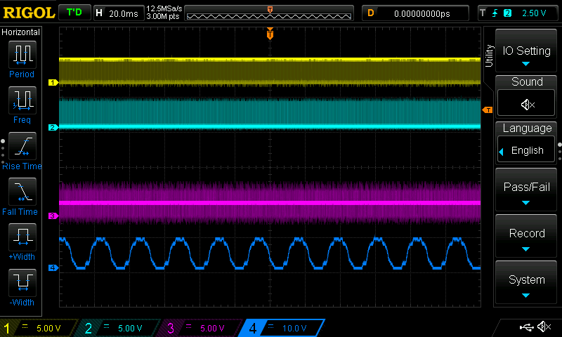
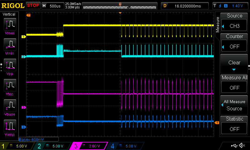
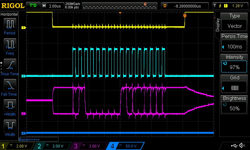
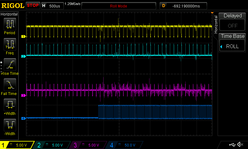
First, if the sensor is plugged in when power is applied, the odrive board never initializes fully: it will start talking over the USB interface, but e.g. it reports vbus_voltage as 12.0. In all following shots, channel 1 in yellow is the chosen channel select pin, 2 in teal is SCK, 3 in purple is MISO, and 4 is a high-voltage source: either DC input voltage or motor leg C. Using a DS1054Z oscilloscope, I see this kind of waveform when power is applied:


Note the strange behavior of the CS signal on channel 1: it gets pulled up a little bit, but not to 3.3V.

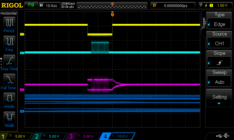
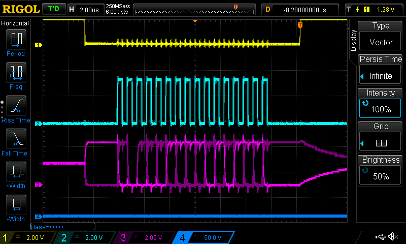
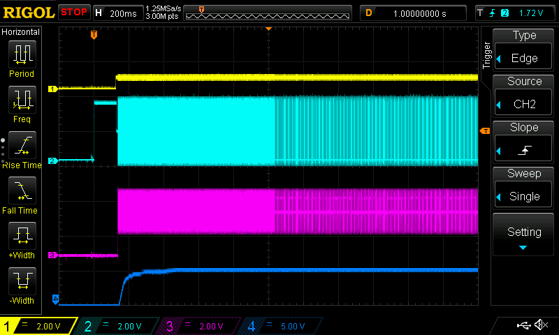
Unplugging the sensor (I currently have it connected via an RJ-45 connector) and re-plugging it fairly soon (maybe within 1 second or so) allows startup to continue, so this isn’t a deal-breaker in the short term, but this is obviously a problem for minimal-intervention system startup :slight_smile: This is what the scope shows when I have initialized the system manually in this way:

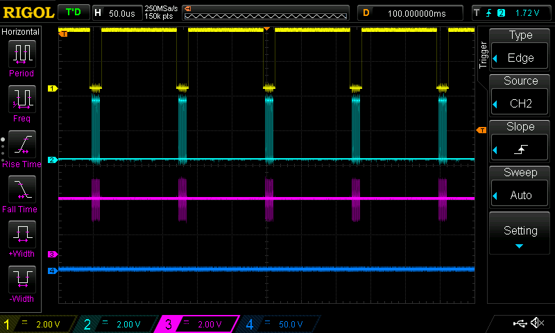
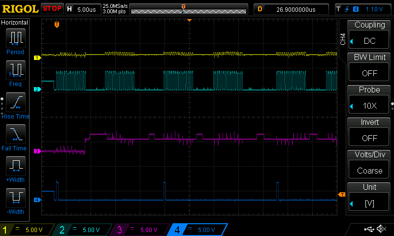
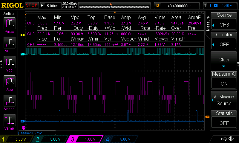
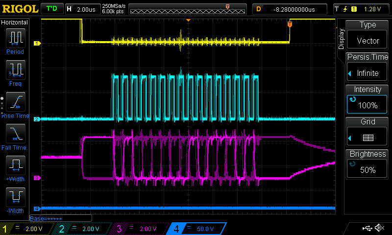
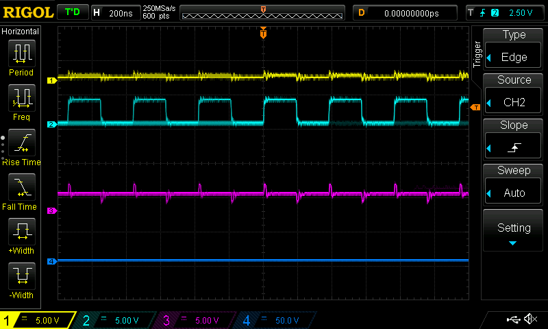
Second, once the system has successfully initialized, attempting to perform motor calibration fails due to EMI. When I set odrv0.axis1.requested_state = AXIS_STATE_FULL_CALIBRATION_SEQUENCE from odrivetool, I see this behavior in the oscilloscope (channel 4 is leg C):


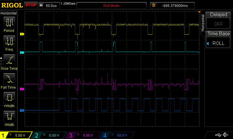
As you can see from the second grab, there is a strong 48 kHz frequency in the SPI bus wires, caused by the MOSFETs switching on and off.

I have shielded the motor wires with some metal braid, and also shielded the sensor wires, but it has not reduced the noise noticeably. Here’s a picture of the wiring:


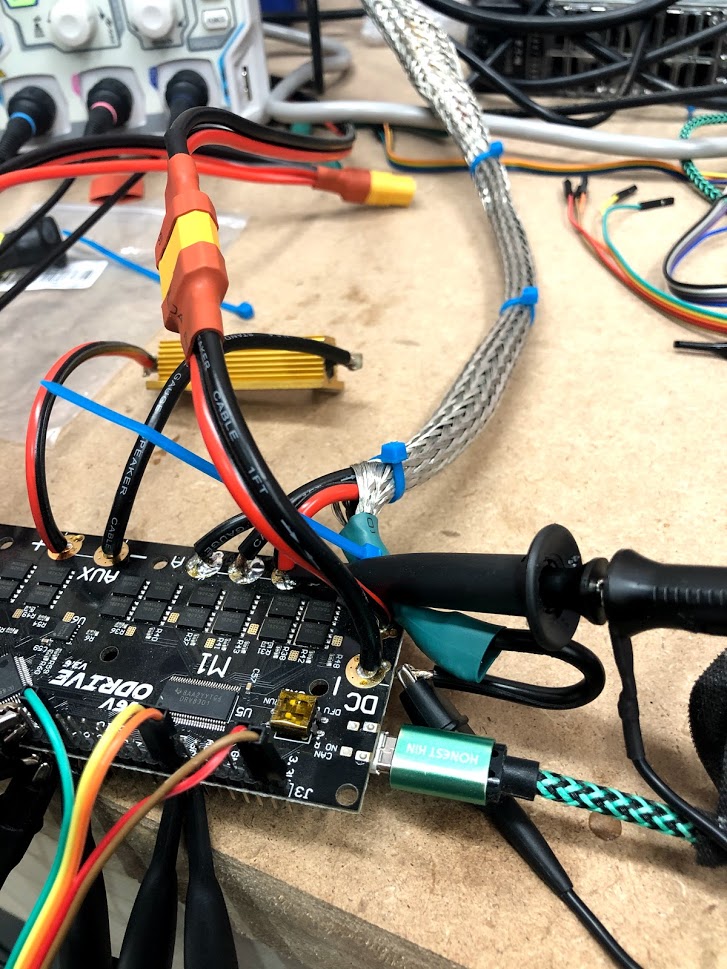
The XT60 connector is input power, the braided cable goes off to the motor, and the dupont connectors
go to an RJ45 and then on to the angle sensor.

What sort of changes or diagnostics would you suggest next? Any pictures of the setup, logs from odrivetool, or anything else I can provide are available for the asking. Thanks very much for any input!

Hi,
Mainly replying because I’m interested in what you are going to find out.

What do the signals look like when you turn the motor by hand? (With and without motor leads connected)

Good luck!

I spun the shaft of the motor with a hand drill to get consistent speed, and saw basically what I expected. With the motor connected to the odrive, a reasonable sinusoid from one of the motor legs:

and no interference on the SPI bus:

With the motor disconnected, there was also no noise visible on the SPI bus.

Another thread I observed: Calibration fails with absolute encoder: Using AS5048A, error symptom is “When I trigger calibration the motor moves slightly and then stops. Calibration never completes”, resolution was to increase resistance_calib_max_voltage. Mine was set to the default 2.0, I increased this to 20V = vbus / 2, and did not observe any change in behavior.

The encoders documentation doesn’t mention any passive components recommended when using the SPI bus, but I note that the MISO line is floating at some middle voltage. Should I perhaps add a pull-up or pull-down resistor to it? Would a ferrite bead near the odrive help? Some capacitance somewhere, similar to that recommended for hall sensors?

My configuration:

odrv0.erase_configuration()
odrv0.reboot()

odrv0.axis1.encoder.config.mode = 0x101
odrv0.axis1.encoder.config.abs_spi_cs_gpio_pin = 3
odrv0.axis1.encoder.config.cpr = 2**14
# established by counting stops, i should pop the back off and count magnets to make sure
odrv0.axis1.motor.config.pole_pairs = 18
odrv0.axis1.motor.config.calibration_current = 5

odrv0.save_configuration()
odrv0.reboot()

After setting these parameters exactly as written above, I still had the two problems mentioned in the initial post. My firmware is built using the Docker image from 006ac82 (from back when it was just the devel branch, not tagged as rc-0.5.0). I’m running out of ideas without hacking some special purpose features into the firmware - perhaps I can pull some pin high iff the encoder signal is judged “good” and determine if it’s always bad or just sometimes. I noticed that once the calibration fails, odrv0.axis1.encoder.spi_error_rate reports (224 - 1) / (224) continuously, despite the SPI traffic continuing to flow.

What power supply are you using for your bus? Can you look at the bus voltage with the scope as you’re attempting this calibrate? If it’s not super clean you could try some cap filtering.

SPI likes short, shielded/twisted pairs cables. With the motor disconnected your SPI signals look good.

Keep in mind, the same SPI peripheral is used to configure the DRV8301 chips during startup, so make sure you’re not abusing the SPI bus by screwing up their voltages or configuration or anything like that.

Ah, I didn’t realize it was shared, I see that in the 3.5 schematic now. It looks like I could possibly try to use PB3 and PB4 (GPIO8 and M0 Enc A) to expose SCK and MISO for SPI1, but since this is actually a v3.6 board I’ll stick to trying to get this to work on the standard pins.

I put a probe on MOSI and triggered on that at startup. When that went off, I saw this:


The CS line on this trace isn’t related to the SPI signal, so it’s reasonable that it isn’t being asserted, the clock looks good, and the MOSI (which isn’t connected to the AS5047P) looks fine… but the MISO line on channel 3, which is connected to the sensor, is being pulled up to about 2.4 volts continuously:

I can see hints of signal there, it’s being pulled up to 3.3V intermittently, but clearly something isn’t happy.

Next, I added a 10k ohm resistor in series with the MISO line between the board and the cable. Now I get what looks like a successful initialization of the DRV8301s, and 2ms later the 8kHz updates from the sensor begin successfully:


This looks like problem 1 down!

So, back to problem two: the board behaves as if sensor readings are unavailable when calibration begins. I captured the calibration in the same way as in the first post, and interestingly, the visible ringing on the oscilloscope is greatly reduced:


There’s still some amount of a blip in the CS line, but nothing that I’d expect to cause a false 0 or 1 to be read.

Ahhh… I started running odrv0.reboot() instead of fully cycling power, since it’s faster to type than to disconnect the power, wait for the capacitors to drain, and plug it back in. When I reboot in software, I think the DRV8301s aren’t correctly re-initialized: future attempts to run a calibration cycle don’t actually send bus voltage to the motor, and the scope never triggers! I’ll go back to unplugging and re-plugging each time. The most interesting thing about this fact: the calibration process still fails, with the same encoder error! This suggests that I should do some more diagnosis on the software side and see if I can determine why this failure is being triggered.

One more set of animated scope shots; this is the current noise level on the SPI bus during calibration. I don’t think this is necessarily the source of my problems, as described in the last paragraph, but just for my own reference to document the current state of things.

That’s all for now, I hope to return tomorrow and do some more digging.

1 Like

Good catch on the series resistor. Double check the 5047p has the single parity bit and the error flag - that’s what the software is expecting at the moment. If the upper two bits of your transaction from the sensor aren’t [parity][error], you’ll need to put a new encoder in encoder.hpp/.cpp. The noise is interesting. You’re using the grounds on the same header as the SPI pins right?

Yes, I’m using the ground from the same set of pins as the spi bus.

I went and checked the data sheet, and it does the same thing as the AS5048a, and what the firmware expects: parity, then error, then 14 bits of signal. That said, just using a mark 1 eyeball suggests to me that the error bit is set in all the traces I can read it from (unfortunately all are from today). I might connect MOSI and try to add support for reading the DIAAGC register out to odrivetool, which I’ve found to be useful in previous projects. Maybe it all boils down to “check the sensor is actually working”, but if so I’ll try to leave some indicators of what the problem is for the next person to try configuring an absolute sensor :smile:

1 Like

Quick update from my morning experimentation: I used my scope with the “persistence time” setting to capture the SPI interaction before and after triggering the motor calibration sequence. In the “before” view, one can clearly see that the error bit is the only one that’s never been high/1 in the few minutes I left this running:


In the “during” view, the error bit has been both high and low:

and in the “after” view, the error bit is always high:

Looking at the datasheet, I see that the AS5047’s error bit is defined as follows:

If an error occurred in the previous SPI command frame, the EF bit is set high

I think this implies that the odrive should actually ignore the error bit entirely: it never sends commands (MOSI is disconnected on the odrive end, after all!) so this error bit can by definition only be activated by noise elsewhere in the system. I have MOSI tied to 3v3 at the encoder end, but perhaps somehow the interference of a motor spinning up causes that to glitch out?

My next plan is to hook a different microcontroller into the sensor, and see if I see similar error flags being set when the odrive initiates calibration or if it’s perhaps a glitch in how the SPI is being driven during calibration or something.

2 Likes

Hello,

was reading this topic and I had the same sensor with the problem where the error bit was set.

I did not use any shielding in my cables but they were short, about 5-10 cm for the SPI communication. Not using any resistors, just directly plugged all the cables in the Odrive.

I fixed this error by insulating with some tape the screws holding the evaluation board in place, apparently some static electricity from the chassis interfered with the sensor’s error bit, not quite sure about the details but after changing this the odrive did not immediately give ERROR_ABS_SPI_COM_FAIL error at startup.

However this did not fix my calibration problems, as soon as I started the calibration the error bit would be set. Stupidly, the magnet holder on the motor shaft would touch two of the screws holding the sensor in place, and this caused the error bit to be set. I fixed this by shortening the screws and by better aligning the motor.

In short, if you are using this board for your AS5047P sensor,

board

make sure your mounting screws are well insulated from each other and the mounting chassis, as this appears to cause problems with the SPI communication.

Another thing to remember is that this board needs to be changed to the 3.3V setup for SPI, look at this topic to see its caveats, changing the jumper was just not enough.

Hope this helps! Took me two days to find this was a problem with the board I was using.

2 Likes