I’m working on my second project with ODrive (the first one, a motorized electronic trike with hoverboard wheels, went well and is on the back burner for non-ODrive reasons). I decided to try a motor similar to this one: 60V nominal, 2KW max recommended, et cetera. I am using an AS5047P breakout board mounted to the back of the motor. I removed the back plate and added an appropriate magnet (included with the breakout board linked) to the shaft of the motor. I am using a variable voltage wall-power switching power supply, currently set to ~40V for testing purposes, and have installed the devel branch from Github on the board. However, I am experiencing two problems with this setup.
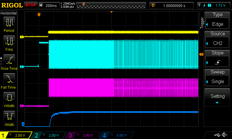
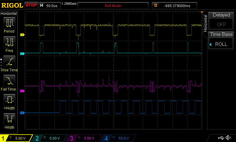
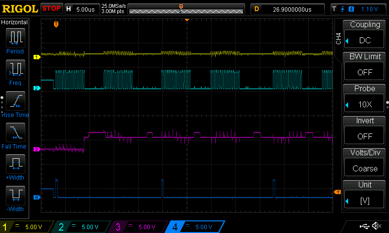
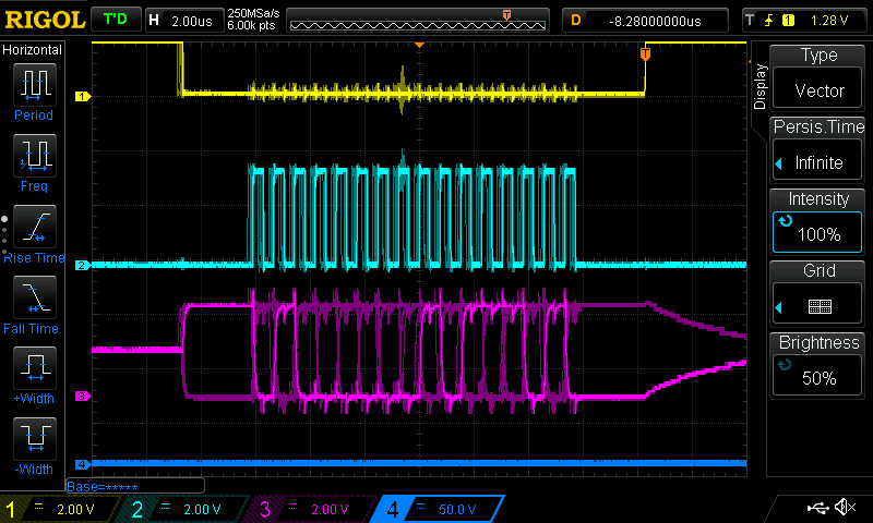
First, if the sensor is plugged in when power is applied, the odrive board never initializes fully: it will start talking over the USB interface, but e.g. it reports vbus_voltage as 12.0. In all following shots, channel 1 in yellow is the chosen channel select pin, 2 in teal is SCK, 3 in purple is MISO, and 4 is a high-voltage source: either DC input voltage or motor leg C. Using a DS1054Z oscilloscope, I see this kind of waveform when power is applied:
Note the strange behavior of the CS signal on channel 1: it gets pulled up a little bit, but not to 3.3V.
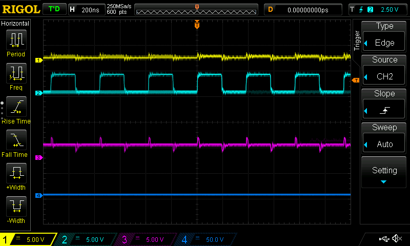
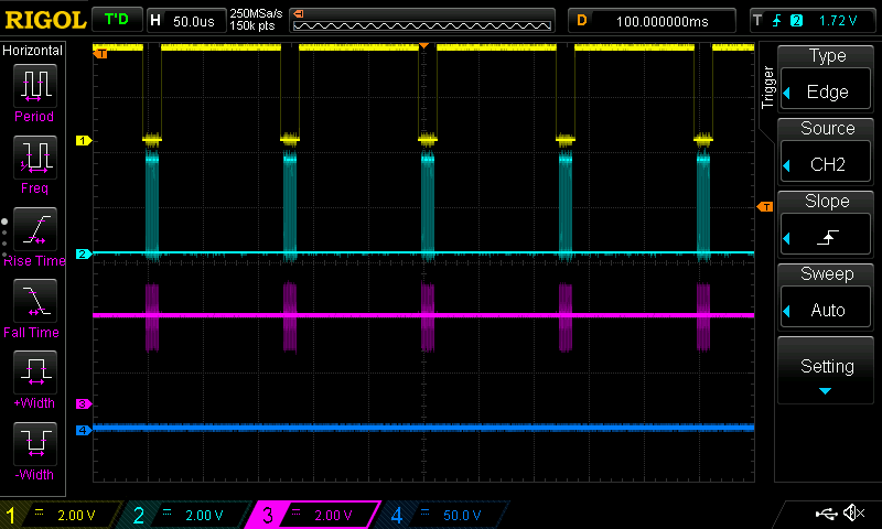
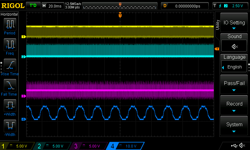
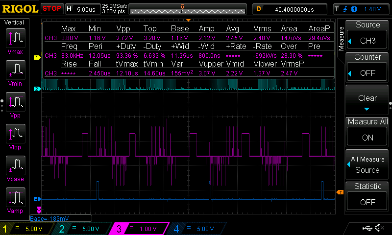
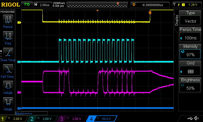
Unplugging the sensor (I currently have it connected via an RJ-45 connector) and re-plugging it fairly soon (maybe within 1 second or so) allows startup to continue, so this isn’t a deal-breaker in the short term, but this is obviously a problem for minimal-intervention system startup  This is what the scope shows when I have initialized the system manually in this way:
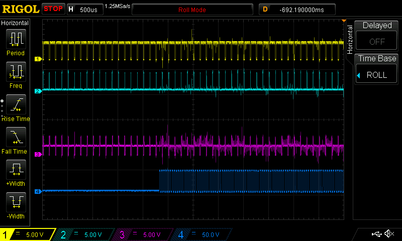
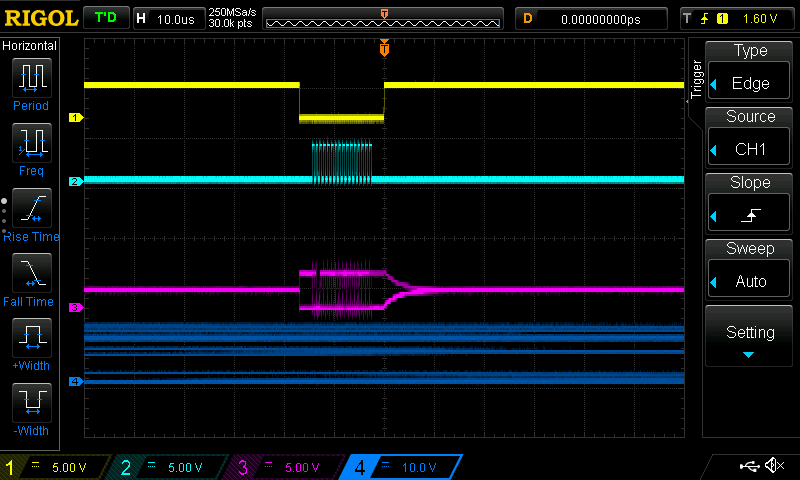
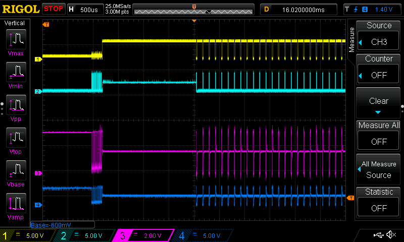
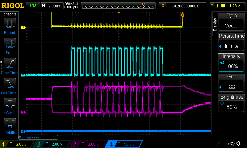
Second, once the system has successfully initialized, attempting to perform motor calibration fails due to EMI. When I set odrv0.axis1.requested_state = AXIS_STATE_FULL_CALIBRATION_SEQUENCE from odrivetool, I see this behavior in the oscilloscope (channel 4 is leg C):
As you can see from the second grab, there is a strong 48 kHz frequency in the SPI bus wires, caused by the MOSFETs switching on and off.
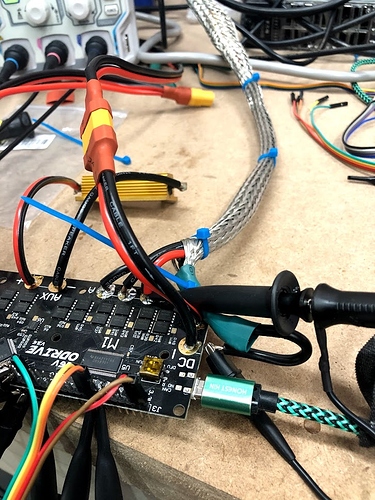
I have shielded the motor wires with some metal braid, and also shielded the sensor wires, but it has not reduced the noise noticeably. Here’s a picture of the wiring:
The XT60 connector is input power, the braided cable goes off to the motor, and the dupont connectors
go to an RJ45 and then on to the angle sensor.
What sort of changes or diagnostics would you suggest next? Any pictures of the setup, logs from odrivetool, or anything else I can provide are available for the asking. Thanks very much for any input!
