Hello Fellow ODrivers,
I am using 2 motor drivers at the moment before I move on to a larger 4 motor system. My current connections scheme looks something like this:
[Computer] → [USB Isolator] → [USB-CAN Adapter] → [ODrive 1] → [ODrive 2]
For the connections between Adapter-ODrive1 and ODrive1-ODrive2 I am using the CAN JST cable from the shop. My ODrive 2 has it’s 120Ohm Resistor switch set to ON as it is the last in the chain.
My problem is that I am not seeing the ODrives/Adapter in the GUI. I can see them if I connect to them directly from the USB Isolator to the Drives but I would like to see them both at the same time in the configurator.
Things I have tried:
- Connecting and reconnecting to see if the device will show up on the GUI.
- Configured the Drives to use CAN for communication
- Updated USB Drivers
Has anyone else run into this problem or have any idea how to resolve it?
Hope to hear back soon,
Emi
Hi! I would make sure that you’re connecting the USB-CAN adapter GND to your system GND at some point – the CAN GND connections in the S1 are just an internal passthrough. You’ll need to connect the USB-CAN GND to the GND at your system “star point” – essentially where both ODrives connect to the battery or power supply, whether it’s at the power supply or battery terminals, or at a power distribution block.
You could either run a wire from the USB-CAN adapter screw terminal to said star point, or run a wire just from the CAN GND on the last S1’s JST-GH CAN connector to it, like how is shown in the image on the Arduino CAN guide page (though there it shows running the wire to DC- at the ODrive, if you can instead run it to the star point GND it gives enhanced noise immunity).
I’d also make sure that you’re using the beta version of the GUI that supports the USB-CAN adapter, which can be found here.
Okay I tried connecting the CAN adapter GND to my star point and that did not work (but I still kept that connection since I did not have that before). What did the trick was using the beta version of the GUI.
Thank you!
Great! Please let me know if you have any other issues!
Hey solomondg, I am now trying to command one of the two ODrives using a python script running on a RaspberryPi 4 (using the can_simple.py script as a jumping off point).
I followed the setup guides in the ODrive docs for CAN and Python but I can’t seem to find my ODrives when I run odrivetool in my terminal.
Additionally, when I run the can_simple.py script I get stuck in the first for loop which I took to mean the state is not actually changing when requested.
This all leads me to believe I am having some connectivity issue where the ODrives are not being “registered” by my RPi. Do you have any suggestions for me on how to further debug this?
Thank you and hope to hear back soon.
Best,
Emi
ODrivetool currently is USB only, ODrivetool-over-CAN is a few months away.
Additionally, when I run the can_simple.py script I get stuck in the first for loop which I took to mean the state is not actually changing when requested.
Are you sure that you’ve properly configured the ODrive node ID and enabled the heartbeat messages?
You can run candump can0 and see if the ODrive is sending messages.
Okay that makes sense why I could not see anything using odrivetool.
When I run candump can0 I get a repeating set of messages:
can0 041 [8] 00 00 00 00 01 00 01 00
can0 021 [8] 00 00 00 00 01 0E 01 00
I set up the node ids in the configurator to be 1 and 2. I am attempting comms with the node id = 1 Odrive.
If I run candump can0 and then run my script I do see some additional traffic:
can0 027 [4] 08 00 00 00
If I am understanding this right, the 27 is the ID. I am not sure how this relates to the CANSimple message ID (11-bt message identifier). The 08 I imagine is the data sent over the bus (which is the value sent to enter closed loop control).
So looking at these first two messages:
can0 041 [8] 00 00 00 00 01 00 01 00
can0 021 [8] 00 00 00 00 01 0E 01 00
The first has an arbitration ID of 0x41, the second is 0x21.
The CAN ID we use has the bottom 5 bits as the message ID, and the top six as the node ID.
So 0x41 is a message ID of 0x41 & 0b11111 = 0x01, corresponding to the heartbeat message, and a node ID of 0x41 >> 5 == 2, corresponding to a node ID of 2.
Ditto, 0x21 corresponds to a message ID of 0x01 and node ID of 1.
The 0x27 message being sent when the script runs is a message ID of 0x007 ( Set_Axis_State) to node 1. the 08 is the desired axis state, corresponding to closed loop control, so it should be putting node 1 into closed loop.
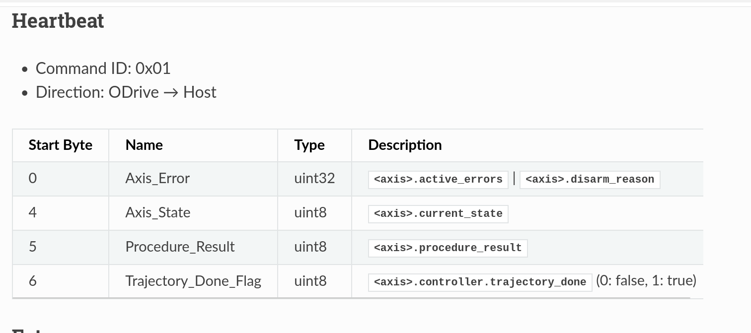
However, if we look at the heartbeat message from node 1 again, we can see the data payload is:
00 00 00 00 01 0E 01 00, corresponding to this mapping:
Here, it looks like procedure_result is 0x0E, and if we look at the procedure_result enum then we can see that this corresponds to the NOT_CALIBRATED error.
So my best guess is either:
- You haven’t fully set up the ODrives in the GUI (e.g. run through all the steps in the final configuration tab, where you apply settings and then run calibration then save the config
or
- You’re using an incremental encoder, or an incremental encoder with index, both which requires some action to be taken before you can enter closed loop (encoder offset calibration and index search, respectively).
The can_simple.py script generally assumes your ODrives are already calibrated/tuned, and can safely be put in closed loop velocity mode. If you want an example for how to run calibration over CAN bus, you can check out can_calibrate.py.
Thank you for the response. It was very helpful and I feel more equipped to debug future problems I may face.
I have the motors running now using the can_simple.py script.
When I turn my system off, will I need to run a calibration sequence each time I turn it back on? I see the default is the FULL_CALIBRATION_SEQUENCE. I may need to look for other calibration types that better suit my application.
Also, I noticed in the GUI whenever I finished a calibration my absolute encoder position was set to 0. Is there a way to avoid this? I am building a robot arm and would like the absolute encoder positions to persist.
If these questions seem too unrelated to the original thread I would be happy to put them in another thread.
Again, thank you for all of the help and patience.
Glad to hear I could help!
When I turn my system off, will I need to run a calibration sequence each time I turn it back on? I see the default is the FULL_CALIBRATION_SEQUENCE. I may need to look for other calibration types that better suit my application.
What encoder are you using? As long as it’s an absolute encoder, and you’ve gone through the GUI setup/config/calibration flow (and hit save configuration at the end), it shouldn’t need to do any calibration on startup.
Also, I noticed in the GUI whenever I finished a calibration my absolute encoder position was set to 0. Is there a way to avoid this? I am building a robot arm and would like the absolute encoder positions to persist.
You can use the absolute encoder reference frame to automatically initialize the axis’s position count to the encoder angle on startup. The odrv0.axis0.pos_vel_mapper.config.offset property can be used to change the offset between the encoder angle and the initialized angle.
If these questions seem too unrelated to the original thread I would be happy to put them in another thread.
You’re all good, here’s a great place for them! I’m happy I can help out