Hi,
can someone please explain why my motors drain current (3-10A) even if they are not moving and input_velocity is set to 0? What is the purpose of that?
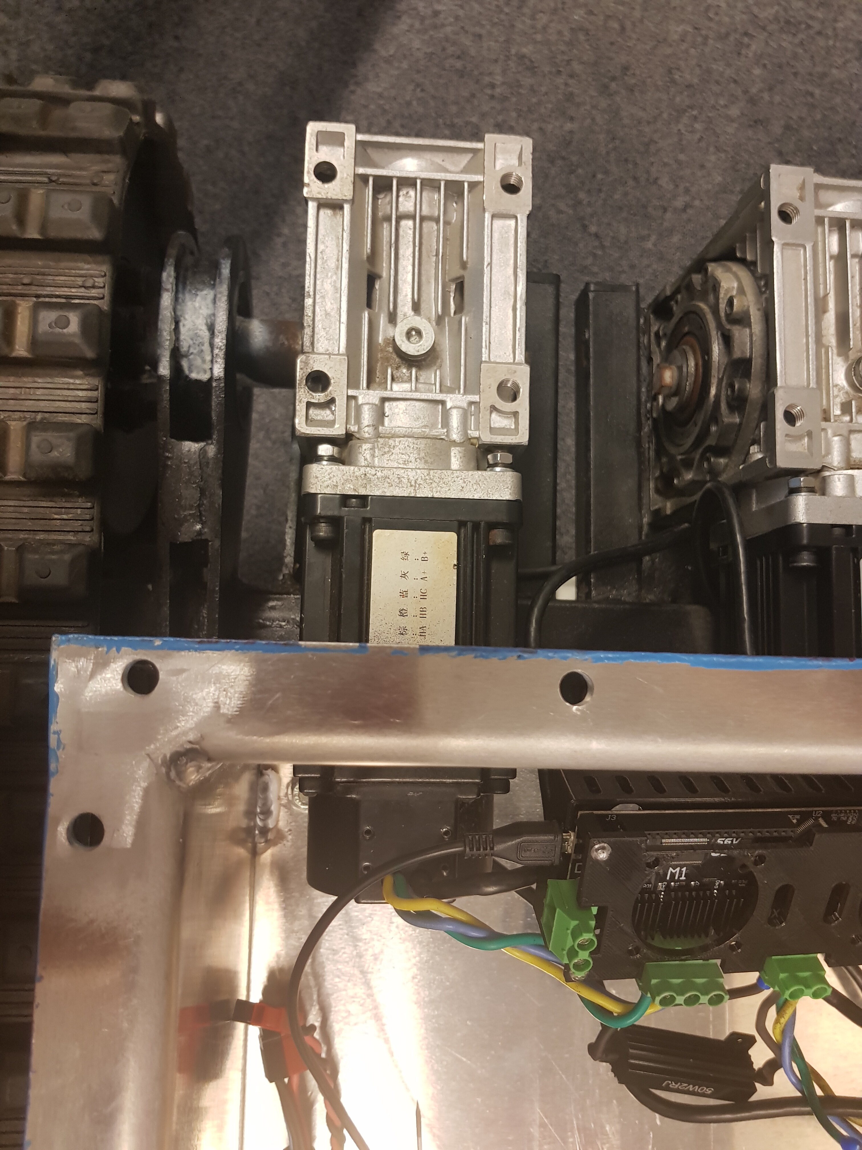
I’m using 2 big hybrid servos with ABZ encoder powering it from battery, and controllers are in velocity control mode. I’m also using velocity ramps.
I’ve noticed parameter named vel_integrator_torque which is exact value as current set point + I can zero it manually. After that current drops to zero. What should I do ? I like the option of using vel ramps and the plan is to drive it using ASCII protocol.
Also, it could be that you have very coggy motors. Some current may be required to “hold position” (ie keep velocity at 0) when the motor is halfway down a cogging detent. Reducing vel_integrator_gain should help to reduce that effect. You can even set it to zero if it is OK for your application for the motor to run at slightly less than the commanded velocity when under heavy load.
You are right, my vel_integrator_gain value is 8. If I remember correctly the higher value helped to run the motor at low speeds and the measured vel doesn’t oscillate around the setpoint.d the measured vel doesn’t oscillate around the setpoint.
errrrr yes iirc the default value is something like 0.0001 for that.
Out of interest, what’s your encoder resolution? Also what ‘low speeds’ are you running at?
If your motors are extremely coggy and you need smooth and efficient constant-speed operation, it may be worth adding some mechanical inertia i.e. a flywheel. What’s your application?
The motors are used to drive differential robot with tracks.
It uses 10:1 worm gearbox and total weight with payload is around 200kgs
(as you can imagine it is really difficult and dangerous to tune the motors)
I lifted the robot and set the gains so the motors would work “in the air” and then I just bumped the gains a bit with robot moving on the ground.
I will try to write down my configs.
The motors are unable to overcome dry friction with less than 25A.
As long as you have a functioning Emergency Stop, it should be safe to tune it on the ground. As you have seen, on the ground it has a very different set of dynamics so motor tuning in the air isn’t really valid.
However, the integrator can be dangerous because of integral windup, so I would advise to set vel_integrator_gain to zero, and tune vel_gain only.
This should be very simple to just bring up from near zero, increasing by a factor of 10 a few times until you see a tiny amount of movement, and tune from there. Maximum motor torque (at stall) will be proportional to vel_setpoint * vel_gain, and will not ramp up to current_lim as it does if you have any integral gain.
You could also change your power supply fuse to something that limits the power to around 50W (which is considered a safe power limit for collaborative robots) - so if your robot takes off for any reason, it will blow the fuse.
At 0.03 ohms motor resistance, 25A ~= 20W, so in theory it should pull less than 1A from the power supply if it’s not moving very fast.
That’s a lot of current to overcome friction though, so it’s no wonder it’s difficult to tune with such a nonlinear plant. Have you tried oiling it?
Leave all that at default (1000?) unless you have a lot of noise on your encoder for some reason (which is very unlikely). If you lower the encoder bandwidth too much, you could screw up the FOC torque controller, i think.
If you get oscillation with the velocity controller, you could drive in torque mode with a velocity limit instead, and set both from your application. That way you might be able to model out some of that friction in your high level controller, if you have one.
Or alternatively send velocity commands with a torque feed-forward value coming from your model.
tried to tune axis0 motor on the ground, vel_integrator_gain = 0, vel_gain=1, input_vel = 3 no movement.
increasing the vel_gain to 10 still no movement live plotter was plotting 90A Iq_measured.
After that I’m getting MOTOR_ERROR_DRV_FAULT on axis0 the same motor works fine on axis1
I have never needed to go more than 0.01 for my gains, I don’t understand why you have to set them so high (unless the units have changed - how fast are you expecting a speed of “3” to be? 3 encoder counts/sec or 3 revs/sec?) - I see you have set up the torque constant for your motor, so there’s a factor of 10 difference there too. I normally leave it at 1 and measure torque in “amps”.
It does sound like you need some feedforward for this motor though! Although a simple linear feedforward might not be enough - you might need to add a constant depending on direction.
Does the DRV_FAULT persist after you power-cycle the drive?
I guess It would be easier to start the configuration again with new board and proper wiring and protections.
Yes the error persists even after recovering my saved configuration.
input_vel = 3 [3 revs/s of motor] that means 0.3 rev/s on the output shaft.
(I’m using the newer one firmware)
Unfortunately I don’t have any kind of documentation. All I know is that the motors are rated at 24V and it is NEMA 32 housing. I had to find out the pinout by myself.
riiight. Ok, I think I may know what your original problem is.
I’m guessing you did not remove the motors from their gearboxes before calibration?
Really, this needs to be done or else ODrive will get a poor calibration, and very inefficient torque production. But in your case that’s difficult to do.
However, I see the motor also has Hall sensors. These do not require a precise calibration and will always give a “good enough” commutation signal, so you would not need to disassemble your motors to use those.
This simply applies a torque proportional to the velocity command (whereas the vel_gain applies a torque proportional to the error between the velocity command and the actual velocity)
If you use both feedforward and feedback gains, their effects are added together to produce a torque command.
so
I omit the integral term, assuming k_vi (i.e. vel_integrator_gain) = 0
Velocity feedforward gain is useful when you have a lot of friction in the system which is roughly proportional to velocity. If your friction does not increase with velocity then it is not so useful.
I use CAN interface and send command set_input_vel(float velocity, float torque_FF).
Confused about parameter - torque_FF. I think, that this parametr can help me solving error between velocity_command and velocity_actual.
That parameter can be used to directly add a torque offset, so instead of being a function of velocity, it adds whatever torque you supply.
You could for example, use the jacobian of your robot to transform the load vector at the end-effector into torque FF commands for each joint