I’m getting unrealistic current measurements for my setup, suggesting a reduction in current required to spin a motor at higher speed (i.e. negative viscous friction). This obviously makes no physical sense, and I am suspecting a current measurement issue.
Specs:
ODrive v3.6 56V version, supplied with 40V
T-Motor 8012, 100kV, 21 pole pairs
CUI AMT233V-A encoder (identical issues with an AMS AS5048 and AS5047P, however).
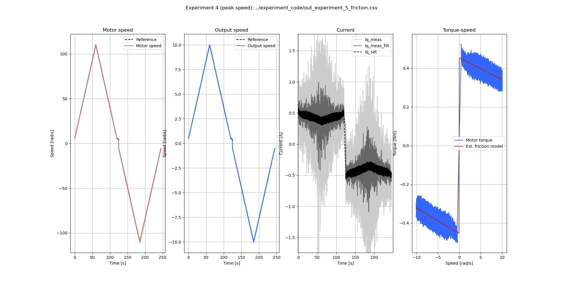
I am running in velocity control, with default gains increased by a factor 2 (although this does not seem to matter). My data, on ramping velocity reference slowly, looks as follows:
with plot 1 the motor velocity, plot 3 the current (reference, measurement, filtered), and plot 4 the speed-torque curve, using motor velocity, current, and the known torque constant. Note that plot 4 uses the current reference, but the measurement shows the same behaviour. Clearly, current magnitude appears to reduce as speed increases , which is not physically possible. Notably this happens at relatively low velocities already (below 50 rad/s or 8 rev/s or 477rpm), which is why encoder limitations don’t seem too likely.
I have previously verified with a known static load (no motion) that the current measurement and torque constant together yield approximately the known torque, i.e. suggesting the current measurement isn’t entirely wrong when velocity is zero. However, it appears that it is when velocity increases. There is obviously quite some noise on the current at these magnitudes, but the trend is still clearly there.
What I have tried:
Different encoders (see above)
Frictional load (a gearbox). This reduces the negative viscous term, but quite often still negative viscous term. I would expect a significant increase in current as speed increases with this load.
Increasing encoder and current control bandwidth from 1000 to 3000 (rad/s? Hz?): More noise as expected, same result.
Reduce requested current to 20A from 60A. No significant difference, maybe less current noise, but identical trend.
Reduce supply voltage to 15V. No difference.
My suspicion is something with either 1) encoder filtering, 2) encoder phase lead/lag, 3) current filtering in software (would have to be before the abc->iq transforms, given that in q-frame current should be slowly increasing with velocity), or 4) issues measuring rapidly changing currents in the phases.
Help would be greatly appreciated! I’d think current measurement is important for many users.
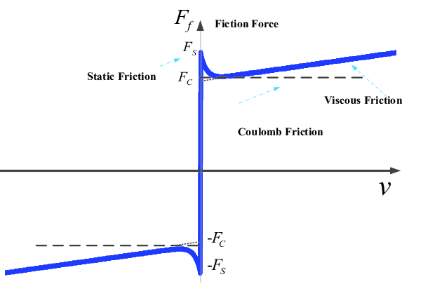
That curve is pretty weird, I would also expect a positive sloped friction value. Even if you model it with a stribeck curve, it doesn’t really make any sense (the negative portion would be tiny in a motor, right?)
I’m not entirely sure what would cause this behaviour electrically. I’ll ask @madcowswe about it, very interesting question! And nice graphs
Thanks for the replies guys! Also a little slow here, Christmas and whatnot
@Wetmelon I have not looked at i_d at all, I’ll do that right after new year’s Indeed the Stribeck curve should be very, very narrow - way below the speeds we’re seeing here. We should essentially see Coulomb and viscous friction terms.
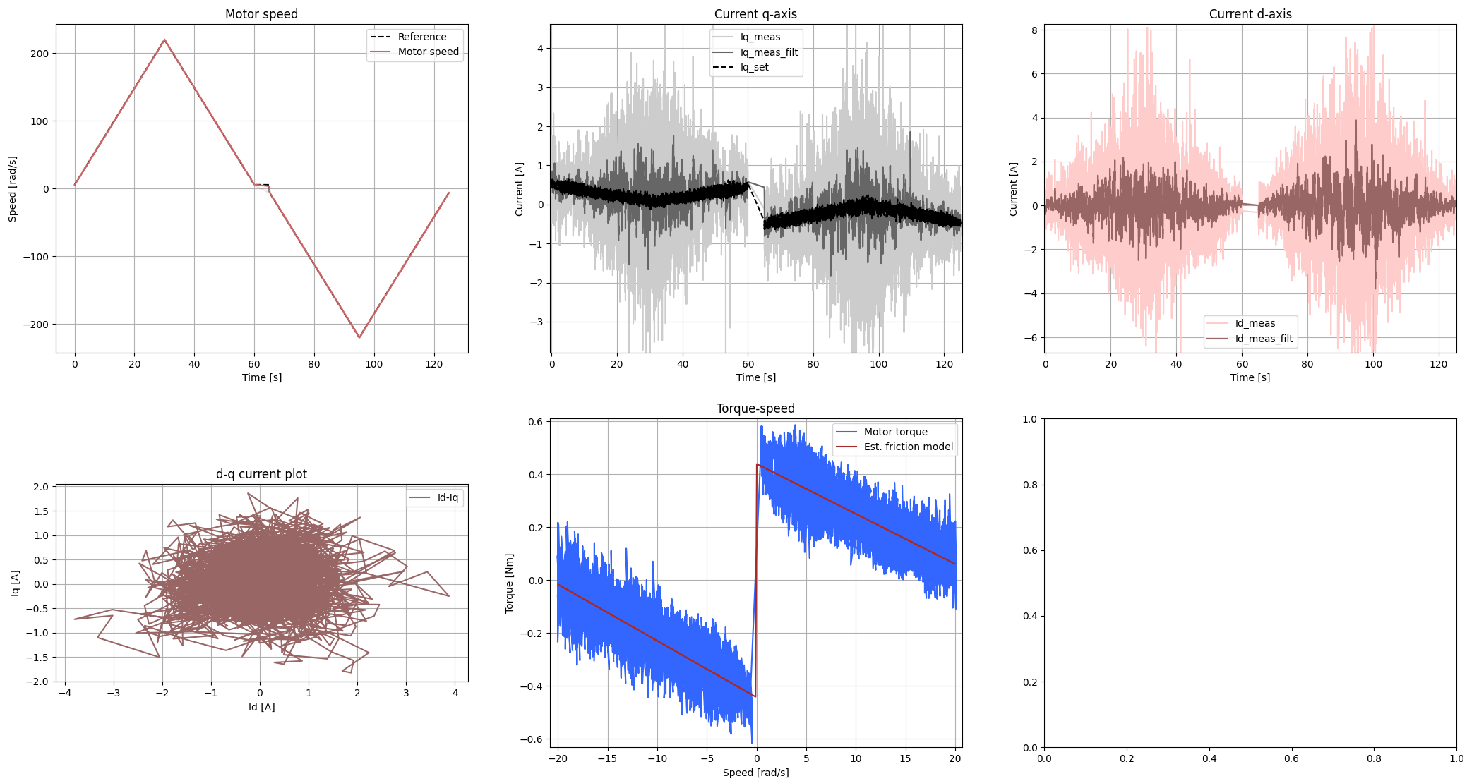
Again the usual reduction is 11:1, so these become:
10rad/s output = 110 rad/s input, which is 6303 deg/s or 1050rpm at the motor.
20rad/s output = 220 rad/s input, which is 12605 deg/s or 2100rpm at the motor.
The Id current appears to be all over the place here, reaching magnitudes higher than the q-axis, even. These speeds are barely up to 50% of the encoder’s rated speed (4000rpm according to the encoder guide).
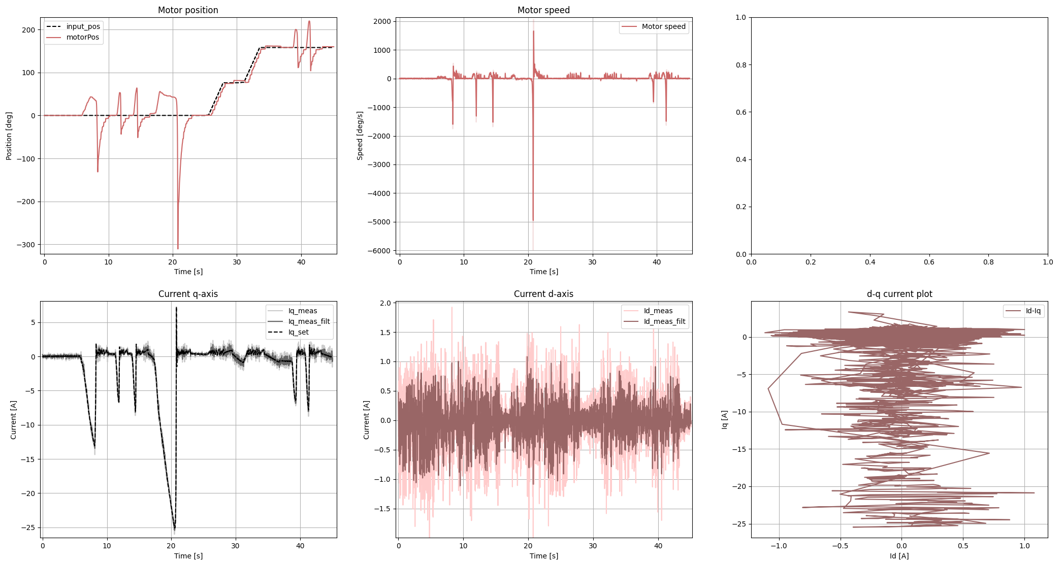
I’ve also done a positioning test, where I move it around a little and deflect it from its desired position by hand:
This one in deg and deg/s as I know you guys prefer it
Interestingly, in this case the d-axis current barely moves at all (comparatively speaking), even in the brief instance where VERY high speed is achieved when I hold the motor off-position for a while and the integral term builds up. At 25A the motor is launched back to the setpoint at up to 5000 deg/s. Yet d-axis current does not move, at least not in the sample time that I can manage over serial.
One thing that does strike me is that the motor spent a lot of time stationary, around Iq = 0, and that d-axis noise seems to be significantly higher than that of the q-axis. I’d expect essentially a circle in the d-q current plot (bottom right), but it’s more like a horizontal ellipse.
This sounds like this motor / encoder combination is giving the odrive trouble (common for T-motors). I don’t suppose you can spin the motor and measure the backEMF to check if it’s properly sinusoidal?
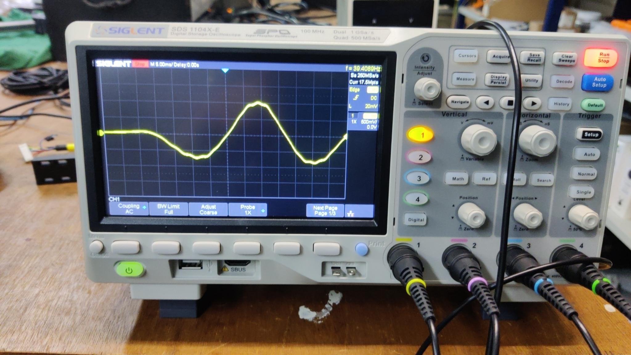
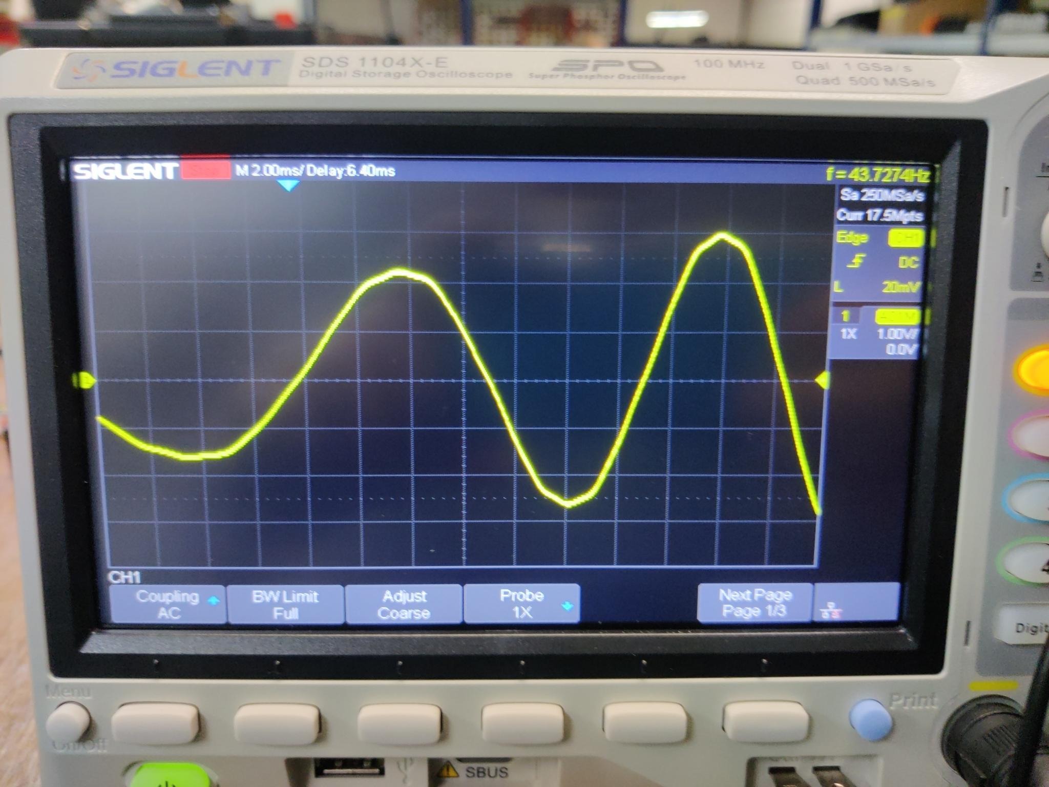
This is the motor being spun by hand with voltage measured across two phases. This looks fairly sinusoidal to me, albeit a little triangular. Would this be enough to cause problems you reckon?
@madcowswe As you know I might get some ODrive Pros - I’m not well familiar with the nitty gritty of this stuff, should I expect differences/improvements in this situation?
Hard to say what exactly is causing your issues, but my best guess as per before is:
The group delay in Pro and S1 is more controlled. We don’t yet have exact compensation for it, but the sample point itself is much better controlled, and is intentionally placed in a good spot. So it may fix the issue already, and if not we can characterize the delay and fix it.