Hi All, I’ve seen several posts where folks are load testing their ODrives but I have not seen a ton on the setup. I would like to test both axis with a 60A continuous current for load testing a new passive heatsink design that should manage continuous load up to 60A in 100F ambient temps.
My current thinking is to put each motor in position control, mount a lever arm off each shaft and load with weight until we hit a current demand of 60A and then leave it there in holding position. Not sure if all three phases will be activated but I can’t seem to think of anything better other than driving our rover up a steep hill but that’s not very repeatable
One way to load test ODrives (or other motor controllers with regen) is to make a “fighting motor” rig. Connect the two motors with a shaft coupling and use one as an active load with regen into the power supply. This way, you can run both axes at fairly high currents and your power supply only has to handle the losses.
@PJohnson thanks for that note. Does the fighting motor’s regen load the mosfets in such a way that you would see similar heat dissipation as if it were driving that load?
Also, what’s the best way to implement this on odrive? Would one put the fighting motor in closed loop position control with a set current limit and set the drive motor to some ramped velocity with a similar or greater current limit?
We have an existing testing setup, I’m considering linking the two motors with a drive chain
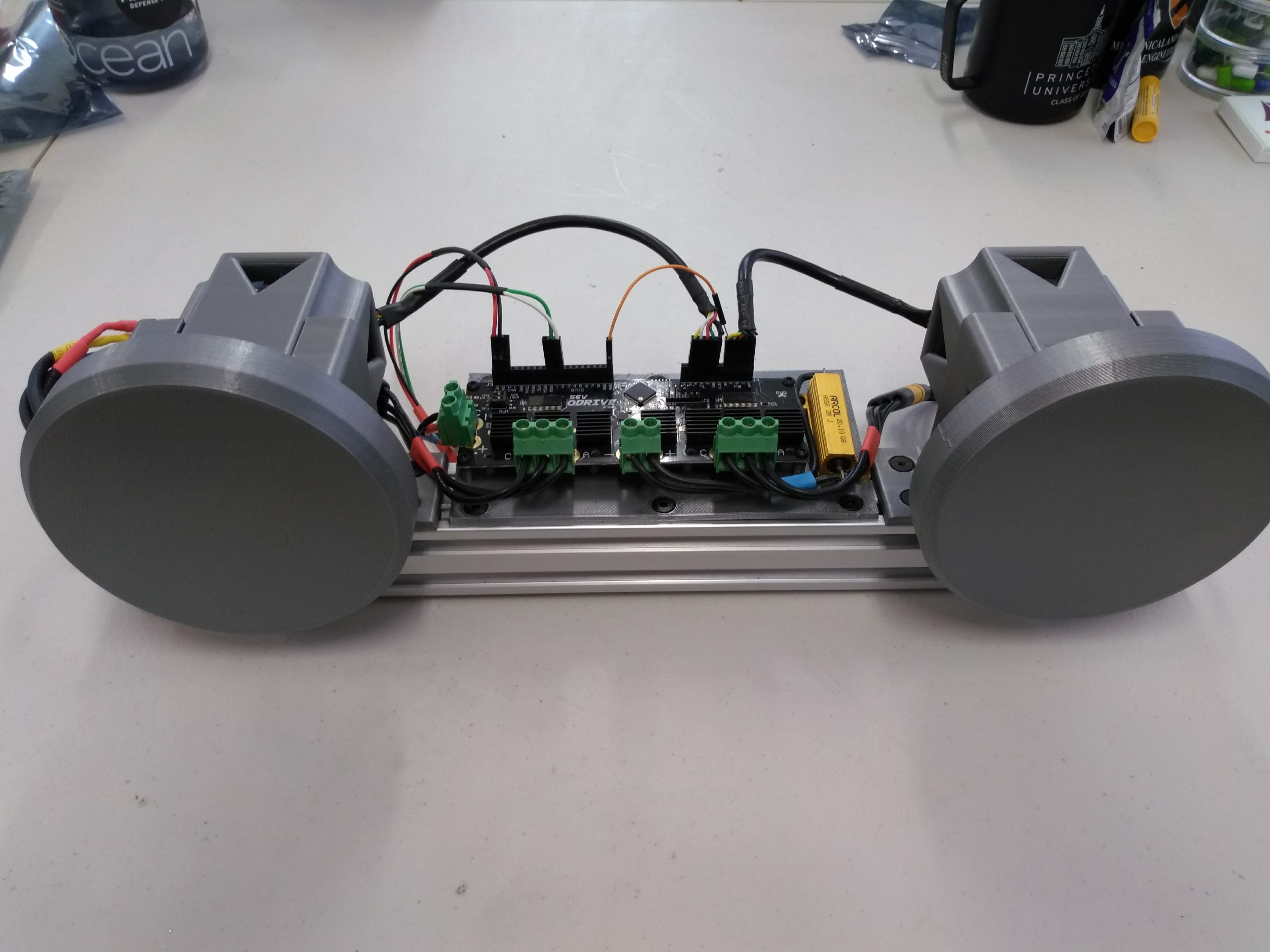
Are those 3D-printed motor housings?
Be careful you don’t melt them with hot motors (especially if they are PLA)
And yes, it would load the mosfets in exactly the same way. The current in the FET bridges reverses around each motor pole anyway. The only difference between forward and reverse torque, is phase.
By doing this you would be generating a lot of current in the DC Link between the two axes on the PCB, so that would generate extra heat too. (holding a static load at max torque wouldn’t do that)
Yeah, that’s how I would do it.
Then you can reverse the velocity to reverse the power flow between the two axes.
In theory, your regen resistor shouldn’t get warm, and the power input from your PSU should be a good indication of drive efficiency * regen efficiency * torque * speed.
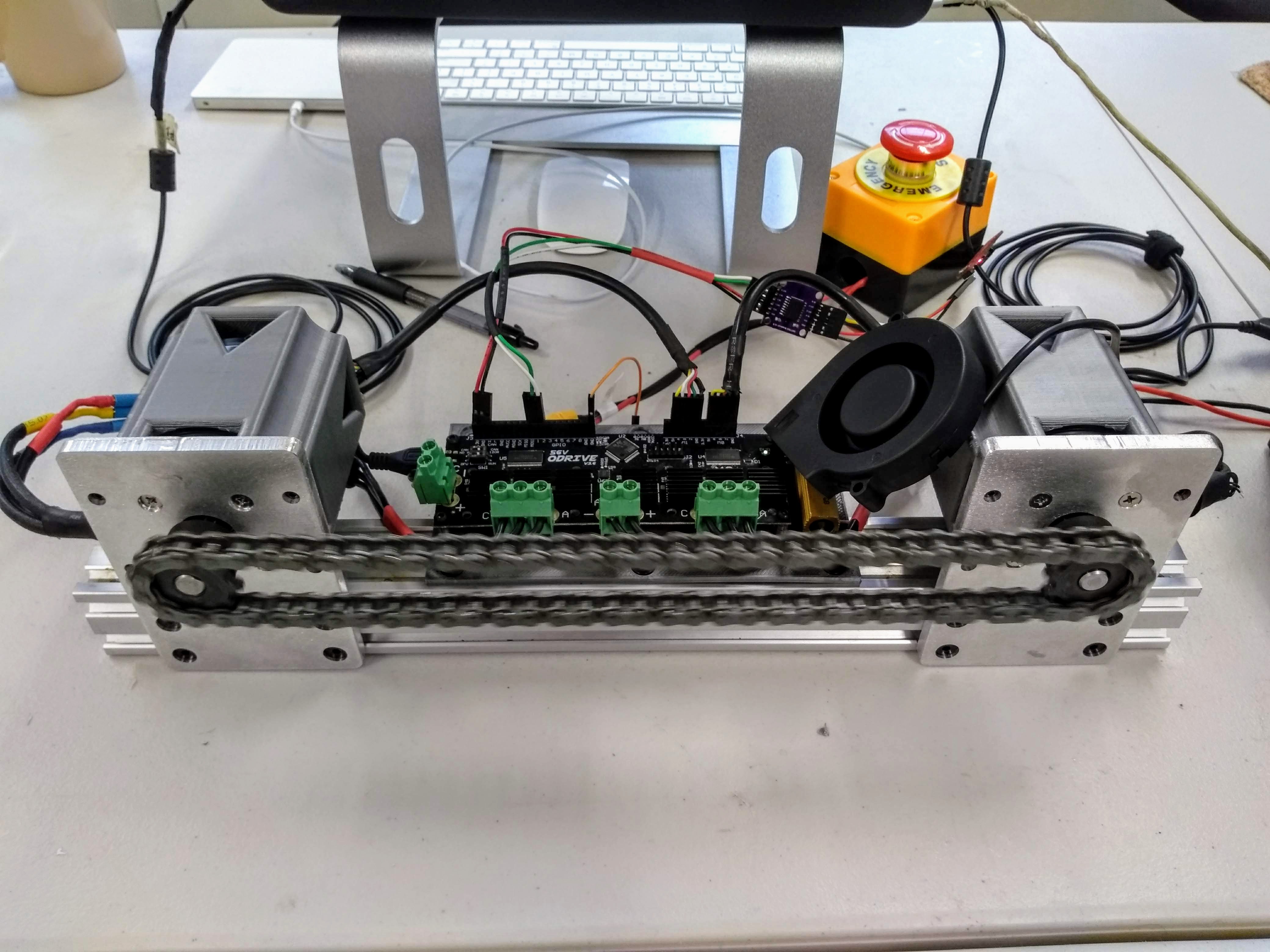
OK,!Thanks @towen for the confirmation on the test setup. Putting some notes here for anyone who wants to reproduce. First, in concept, we set Axis_0 as a drag force in position control and we set Axis_1 as a drive force at a constant velocity. Axis_1 will use slightly more current than the drag motor to overcome the apposing current.
First, we made 2 x motor plates bolted to 40x40 v-slot rail. I’m sure the PETG enclosures we had previously above would be sufficient for lightweight testing but we wanted to have a robust setup. We have a shapeoko and were able to turn these out in about 30 minutes.
Gears, it’s actually hard to find 10mm ANSI gears so we bought these 3/8" ANSI 35 Sprockets from McMaster and used a drill press to bore out a 13/32 hole. We had previously done this with a hand drill and a jig so don’t be intimidated if you don’t have a drill press.
Fan, we’re trying to get a baseline test setup going so fan seemed appropriate to compare against other use cases we want to explore. This is a 75mmx15mm USB Blower Fan from Amazon plugged into a computer.
For the testing protocol, once each motor is calibrated and the chain is connected we are using the following commands in ODrivetool
// First do your lockin, make sure to do one at a time if your chain/belt is connected
odrv0.axis0.requested_state = AXIS_STATE_ENCODER_INDEX_SEARCH
odrv0.axis1.requested_state = AXIS_STATE_ENCODER_INDEX_SEARCH

// Set your drag current on Axis_0 and leave Axis_1 wide open
odrv0.axis0.motor.config.current_lim = 10
odrv0.axis1.motor.config.current_lim = 60

// Put both axis in closed loop control
odrv0.axis0.requested_state = AXIS_STATE_CLOSED_LOOP_CONTROL
odrv0.axis1.requested_state = AXIS_STATE_CLOSED_LOOP_CONTROL

// Set your drive axis to velocity control and start moving
odrv0.axis1.controller.config.control_mode = CONTROL_MODE_VELOCITY_CONTROL
odrv0.axis1.controller.input_vel=1

// Use these commands to confirm current is being applied as expected
odrv0.axis0.motor.current_control.Iq_measured
odrv0.axis1.motor.current_control.Iq_measured

// Use these commands to monitor temperature from ODrivetool CLI
odrv0.axis0.fet_thermistor.temperature
odrv0.axis1.fet_thermistor.temperature
You can certainly log this with liveplotter, we don’t have a setup where liveplotter works so we use an arduino to pull these values and log over 10 second intervals for a predetermined time, typically 10 minutes. We’ll be using this rig to test a passive enclosure design once we have some best case baselines with the fans. Thanks all for your help.