Hi all,
We have a major issue with the Odrive S1’s in combination with the AS5048A (AMS) encoders. These work great in our current custom VESC based design (4 controllers per robot). We have switched to Odrive S1 for our new batch of robots (big stock of Odrive components arrived). But to our surprise the encoders are not read out. After many hours of debugging we might have found the culprit. See the scoped images of the SPI bus:
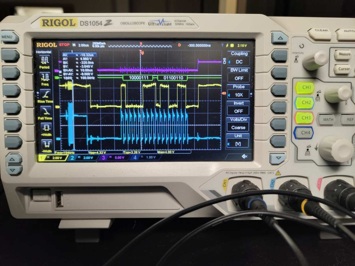
No error:
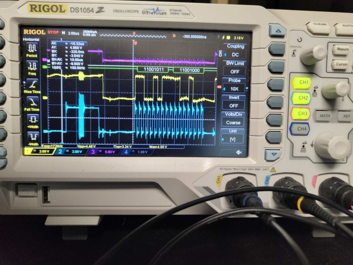
Error:
The encoder works great (when configured). We can read out the position as expected. But once we do any motor related calibration the error flag (EF) of the AMS encoder (second bit from the left, see images) is raised. At this point the Odrive seems to ignore all readings (even if they continue to be send, despite the error flag).
We have designed special differential ended signalling circuits for the SPI bus to minimize the influence of any EMC. This works great on our custom VESC based controllers. Even under high load/currents. But not on the Odrive S1.
Is there anything we can do to ignore the error flag? The source code doesn’t seem to be available. Or am I not looking correctly? Maybe anything else I can try/do to make the Odrive happy?
Looking forward to your reply. Really hope someone can help.
Hi Willem,
Thanks for reaching out!
The S1 will attempt to auto-clear errors that come up on the AS5048A; do your differential circuits also transmit the contents of the MOSI line, or does it hold this high on the AS5048A side? That would explain why the errors aren’t being cleared.
You could also try reducing spi_encoder0.config.baudrate and see if this helps, e.g. if it’s a signal propagation delay issue (I believe the default baudrate is about 1.5MHz, some differential transceivers may introduce significant clock skew) – though it does seem like that’s not the case, if this is only happening after starting motor calibration.
S1 firmware is closed source, however we can make it available under an NDA in some cases – feel free to shoot an email to info@odriverobotics.com and we can chat. Alternatively I’m happy to send over a build that ignores the error bit, if that would be a shorter-term solution that works for you. Generally we recommend our OA1 encoder, which communicates over RS485 (and is thus quite resistant to EMI).
Hi Solomon,
Thanks for your help!
The MOSI line is indeed pulled up with a pull-up resistor. Hence the MCU cannot clear the fault itself. As this would require even more signal lines. We already have 10 (2x temp, 5V, GND and 6x differential SPI lines for CLK, CS and MISO). They are running over a (currently static) slip ring.
I tried the reduce baud rate/CLK to 1MHz and 500kHz. No difference.
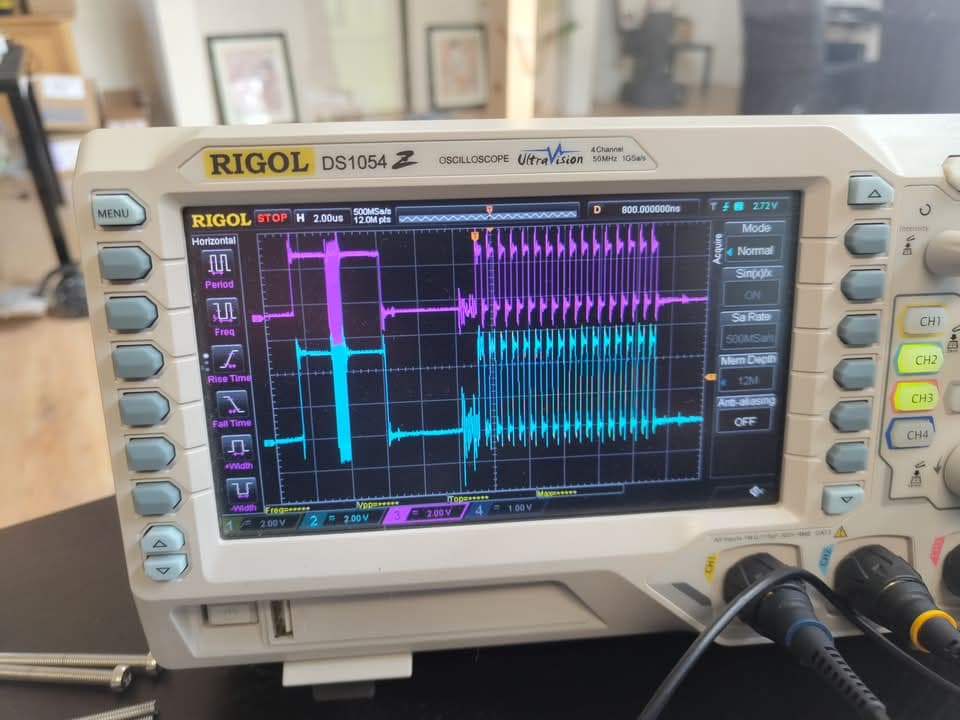
Also did more debugging and testing. There seems to be some ringing/noise introduced during motor calibration. See image below of the CLK signal:
I increased the pull-up resistor for the CLK signal on the encoder PCB from 10k to 4.7k. This worked! The initial motor calibration (measuring inductance and resistance) now successfully completes. No error flag on the encoder anymore.
But when I do encoder offset calibration the error flag is raised again.
Then I also increased the pull-ups on the MISO and CS, and also on the unconnected MOSI pin (all on encoder PCB. No luck…
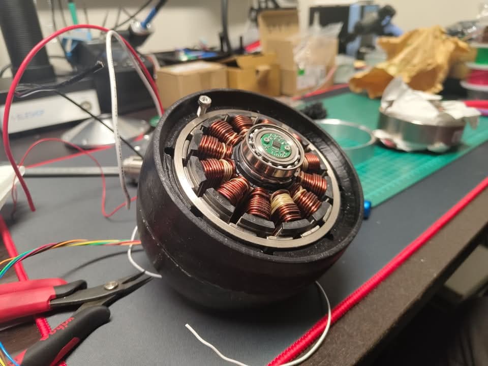
Unfortunately the AO1 does not fit in our motor design. To tight spacing. See below.
Our last hope is changing the firmware. I have mailed you on info@odriverobotics.com earlier today.
It would be great if you can already send over a modified firmware which ignores the error flag/bit!
Thanks again for your help.