hi guys I’m a simple robotics enthusiast who gets along with 3D mechanical modeling and I also deal with 3D printing.
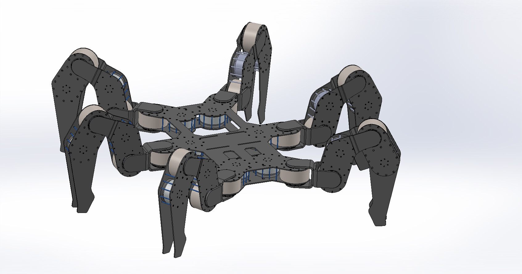
recently I saw that someone started the project of a robot dog using the overboard recycling bldc piloted with the odrive, and having always been a lover of hexapod robots, I came up with a crazy idea, that is to create a giant hexapod robot " “that can be” ridden "by a person.
I state that in programming I am an absolute sucker if not for small things with arduino but I wanted to present my idea of extreme modding of these brushless.
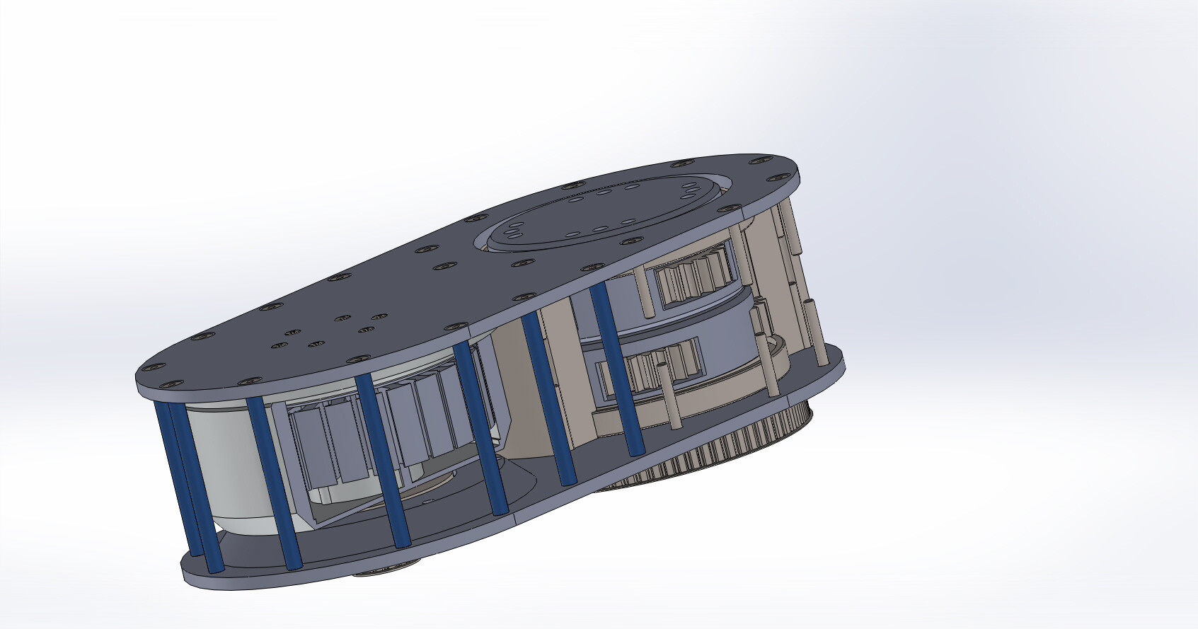
my idea is to completely remove the lips that hold the rubber facet the front part of the bell and drill it for coupling with a pulley, furthermore it would be enough to make a support that fits into the stator with a radial bearing and a support to add to the plug. in this way the annoying axis that increases the dimensions is eliminated. (obviously everything should be done with the help of a lathe)
from here on, the reduction stages start:
1 toothed pulley (it is possible to vary a lot the configuration of all the components for now and only a draft to make the idea). they currently have 16 and 72 teeth
2 first epicylloid stage
3 second planetary stage.
Actually both planetary stages are identical in ratio and gears but even here it is enough to vary the solar and planetary to vary the ratio. (solar 12 satellite 19 corona 50 module 2)
now i would like an opinion from the experts:
first I found some specs found by a guy in the community who tested these brushless and found that they can go at a maximum speed of 300 RPM for 10 Nm of torque.
currently considering 0.19 ratio for single planetary stage and 0.22 for pulleys, a reduction of 0.008 is obtained,
that by considering the maximum values shown above we should get about 2.4RPM and about 1250 Nm which should correspond to about 125 kg per single engine. (Probably it is very exaggerated as a ratio but I repeat and all completely modifiable and modular)
now I would like to ask you how can I calculate the approximate torque needed to support a maximum load of 100Kg?
considering that the robot has 6 legs but in movement conditions the minimum on which it rests are 3 should we consider about 35 kg per motor? which would greatly simplify the system by bringing the ratio to 0.02.
anyway guys give yourselves your opinion advice critical suggestions and all welcome.
i know the project is crazy but it’s just for fun and if i can get the engines from the waste dumps i will probably try to make it.
I hope for some of your opinion
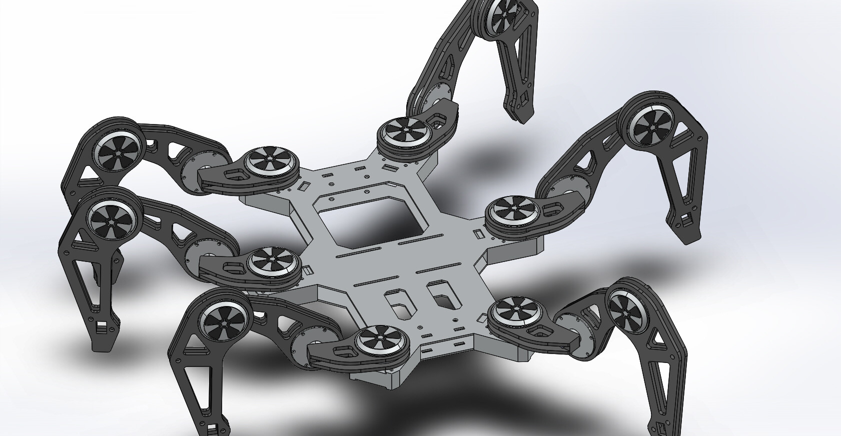


P.S. the design of the robot is just to understand the idea but in the real project you need the gearbox I presume.
however the whole reduction system is easily modifiable and completely modular every single part can be taken and overturned the whole second stage of epiciloidal reduction and so on can also be removed
 , however I try to keep the post updated with another modeling image on what the complete robot would look like in reality. all parts would be easily made by plasma cutting on cnc with 5 mm sheet metal. I hope for some opinion even if I doubt to receive answers