Here is a simplified version of how they do it on ODrive V3.6 Brake Resistor Circuit. The microcontroller varies the duty cycle of a 20kHz PWM signal switching a MOSFET to essentially create a variable load which regulates the bus voltage and dissipates the power from braking. You can monitor your power supply voltage and when it rises above a threshold you gradually increase the duty cycle going to the MOSFET.
You can use an S1 as just a brake resistor driver. Or drive a lower power axis with it at the same time.
You just need to put a high curren shottky diode between the power supply and the ODrive shared DC bus, and then the S1 can dump power reactively to the bus voltage. You do need a fair bit of bus voltage margin for this.
Oh this suggestion mostly makes sense if you have lots of axes. Say you have 6 axes powered by ODrive Pro, and then a single S1 to act as the power management module (together with a shottkey diode to protect the PSU).
This is something I would have to monitor over a longer period. If it’s more than just a peak going +40A there are two hardware related workarounds. The motors are geared down, so one thing would be to increase the reduction gear ratio (which we might do in any case). The second thing would be to increase the system voltage from 24V to 48V. But here’s the question how reliably the S1 can handle load at the nominal limits?
We fried already one v3.6 24V odrive with 24V system voltage.
Hi @madcowswe,
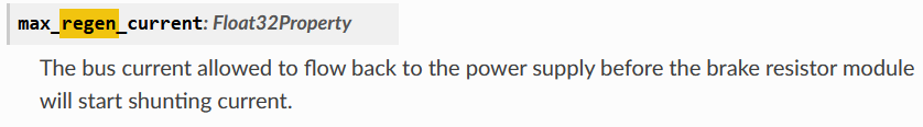
I already bought an Odrive Pro and I get the DC_BUS_OVER_VOLTAGE, I see a spike in the voltage and that’s caused because I have no resistor to dissipate this power. So what you are saying is that there’s no way to add a resistance or there’s no onboard resistance with the Odrive Pro ? Because in the doc there are some parameters related to that brake resistor, but I can’t find how to implement it with the Odrive pro.
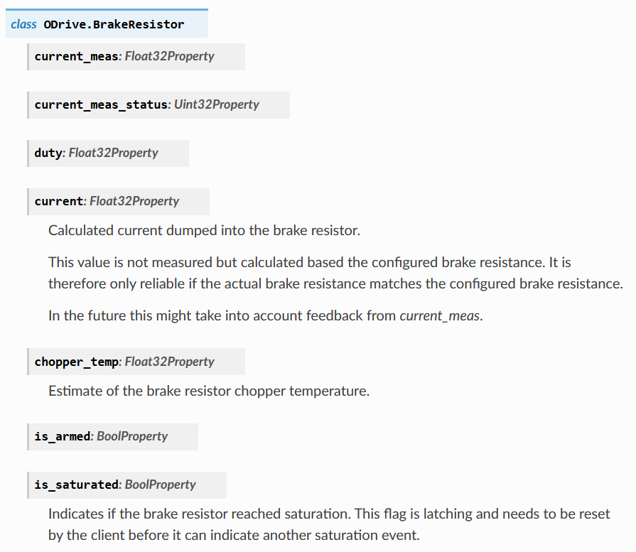
I found those parameters in the doc for the Odrive Pro.
There is no brake resistor circuit on the ODrive Pro. The documentation you are seeing is shared for both ODrive Pro and ODrive S1. The ODrive S1 has a brake resistor circuit.
I get that, but how am I supposed to deal with regen, because when the motor spin in the opposite direction of which the torque is applied, I get a spike of Voltage and then I get an error for over voltage. I think the easy solution would be to have a brake resistor to get rid of the over power ?!
If that’s not possible, what would be the solution with an OdrivePro ?