Hey all,
I just got my first ODrive 3.6 and BLDC Outrunner motor. The motor is an Alien Power System 8318 (https://alienpowersystem.com/shop/brushless-gimbal-motors/8318-outrunner-motor-25kv/) with low kv and high torque. I want to control the motor with an “AS5047P-TS_EK_AB” absolute encoder. I connected the A, B, GND and 5V of the encoder (after doing the 5V solder fix) and set up everything according to the Getting Started section of the ODrive.
When I try to run the Calibration Sequence, the motors turns just a little bit and then stop. I have to restart the ODrive in order to retry the Calibration Sequence. drv0.axis0.requested_state = AXIS_STATE_CLOSED_LOOP_CONTROL does not do anything, the motor is free to turn by hand.
I get following errors (dump_errors(odrv0)) after trying the calibration sequence:
system: not found
axis0
  axis: Error(s):
    UNKNOWN ERROR: 0x00000040
  motor: Error(s):
    MOTOR_ERROR_PHASE_RESISTANCE_OUT_OF_RANGE
  sensorless_estimator: no error
  encoder: no error
  controller: no error
axis1
  axis: no error
  motor: no error
  sensorless_estimator: no error
  encoder: no error
  controller: no error
This error normally occurs if the motor is not connected properly, e.g. the wnding is open or short circuit. That motor (8318s) is well-sized for ODrive and shouldn’t pose any problems.
Have you checked the resistance with a multimeter? Is it plugged in to the right axis?
The motor turns like 2-5° when i start the calibration sequence, so it must be the right axis, no? The encoder is also on the right axis, as I can read the values.
I measured the resistance between (all) two phases of the motor and my multimeter showed me for each 0.05 Ohms (only 2 digits possible), so that also fits with the datasheet.
I just realized that I might have messed up the wiring order of the 3 phases, if that is possible. May it change something if I swap two phases?
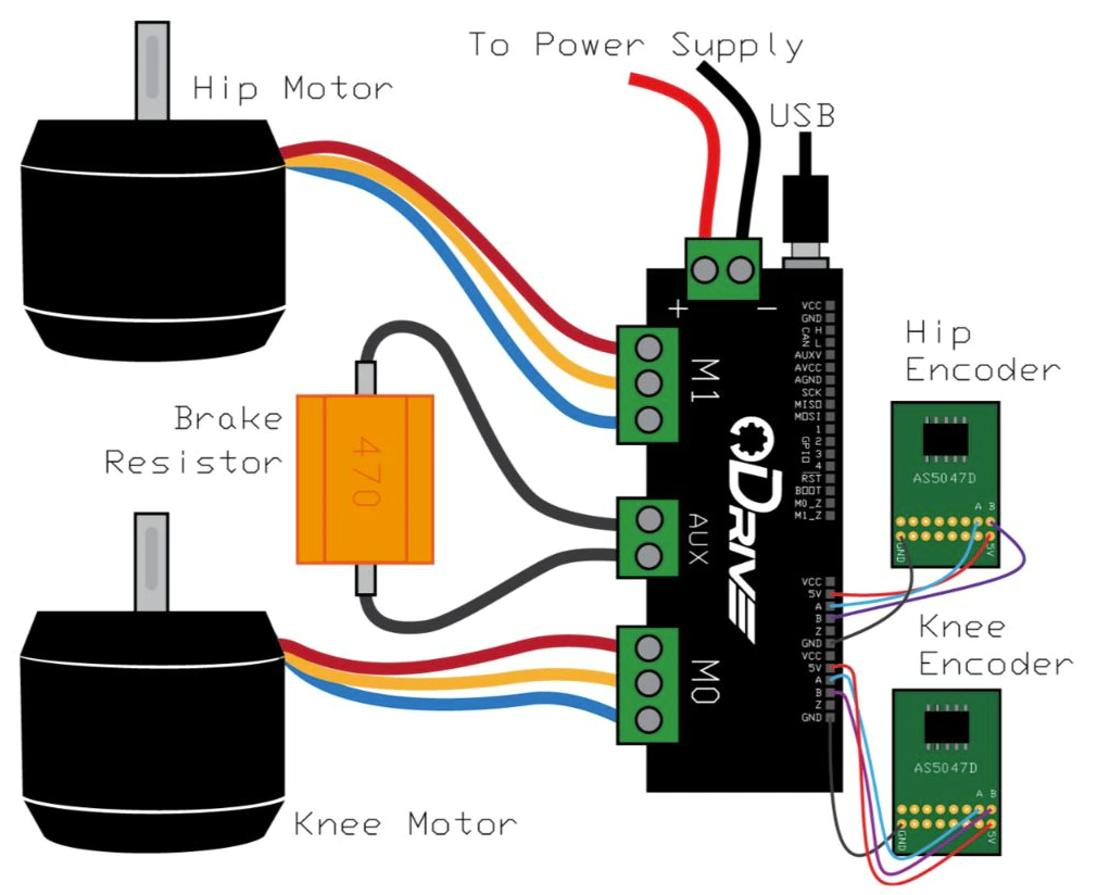
Also another short question: I read a lot that you use odrv0.axis0.encoder.config.mode = ENCODER_MODE_SPI_ABS_CUI or AMS when using the AS5047P. Why does it only work for me without these command? I wired the sensor like this:
No, that doesn’t matter, the order is delected on calibration.
I’m surprised you are getting PHASE_RESISTANCE_OUT_OF_RANGE if it turns. Normally that error would be thrown before the ‘beep’. Are you sure you don’t have another error?
Also, have you tried using the ferrite rings?
That’s because you have wired up the incremental ABZ outputs from the encoder, not the SPI.
If you were to wire up MOSI, MISO, SCK, CS instead of A,B,Z then you would need ENCODER_MODE_SPI_ABS_AMS. This would also allow you to skip the calibration / index search on start-up, which might be necessary if you are unable to detach the load.
Thanks for the clarification.
When I start the calibration, the motor only rotates a little bit (like 5 to 10 degrees). There is no beep.
Reading the error before the calibration shows no error. After calibration I get the above mentioned errors. After rebooting, the errors are gone again and I can start the calibration process again with the same results. Sometimes the motor only jitters shortly, so he tries to do something.
I did not buy the ferrite rings, so no. I did not tried using them.
yes, I changed the value to “10” and that fixed it. Now it does everything as it should be. Thanks a lot!!!
Maybe you can also give me some further advise:
When I put the motor into closed loop position mode, it holds the position. When I rotate more than 1 revolution with odrv0.axis0.controller.input_pos = 1, it overshoots the position by something like 20 to 30 degrees and then slowly and jerky goes to the correct position.
What may I need to adjust in the system in order to get it more accurate and not overshoot the designated position?
Follow the tuning guide. Basically you have too much integral gain, and not enough proportional. The integrator is winding up slowly to correct the error in the proportional controller.
I normally do something like this:
Go to velocity mode. Set vel_integrator_gain to 0 and increase vel_gain until you get vibrations when starting or stopping. Then reduce it by a factor of 4, and go to position mode. Increase pos_gain again until you get vibrations when starting or stopping. Reduce it by a factor of 2. Then increase vel_integrator_gain until the accuracy of the final position is acceptable i.e. no steady-state error. YMMV etc.