I’ve been confused as I thought some people were saying calibrate with load, and others saying that’s invalid and you need to calibrate without load. After further reading I think I understand, but can someone confirm:
I have a hoverboard style robot (hub motors but they have 3200cpr incremental encoders). I need to do FULL CALIBRATION SEQUENCE with no load, suspended. and then save it (how?). Then, I need to ‘tune’ the controller vel, gain, pos gain, vel int gain while the robot is on the ground, with position control, eg 1 rotation and tune it as per docs increasing vel gain until shake, reduce, and increase pos gain til overshoot.
Is that right? I calibrate suspended, one time. Then I tune on the ground, one time. then, each boot i guess robot will spin left/right a bit for a ‘recalibration’? is that last part OK? it’s quite a problem to ‘suspend the robot’ after each power off.
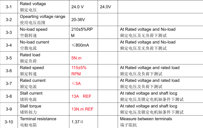
Other question is about current. Wheel says stall current is 13 amps. Does that mean I should set my current limit to 13 amps? and requested range to eg 10 amps with 3 margin?
Unfortunately that’s what you get with incremental encoders. If they have an index pulse, then you may be able to just push it along a bit until it finds the index pulse.
Current limit should be set to 13 amps, yes. But the requested range must be higher than the current limit PLUS the margin (e.g. you can set it to 20A) otherwise the sensor can saturate.
@towen Thank you. about calibration, I know there is a ‘scan distance’.
for an incremental encoder, what is calibration really doing? can the scan distance be lowered?
or what really are the consequences of doing calibration while on the ground (20lb differential robot where wheels are half the weight).
and can we send a ‘fake’ index pulse? why does it really need to line up if there is no ‘index’ anyways? if we’re just finding the pole positions, why does being under load matter? And if we are measuring current/vel/torque characteristics of motor, why can’t this be stored?
Yes you can lower the scan distance with encoder.config.calib_scan_distance.
These are synchronous motors - they need an accurate position feedback or they don’t work. You can’t send a fake index pulse because then you will have incorrect position info, and the motor won’t be able to produce torque.
The calibration works by setting up a magnetic field in the motor, and assumes that there is no load, so the motor will align to that position like a compass. Then we can move the field and see how many encoder pulses corresponds to this coil, and how many more for the next coil.
If there is a load, then it will not align to the direction of the field, but will get pulled in the direction of the load. So it will end up with incorrect position information again.
How do hoverboards work? They don’t require holding up in the air every time you turn them on do they? (do they have absolute encoder?) We could store ‘pulses per coil’ one time, and with incremental encoder there is no correct ‘position’ (for a wheeled robot) it’s just relative. So it would seem that by just rotating the magnetic field until motor produces torque, it could detect what part of a coil it’s in during the first movement and be calibrated without any need to suspend in the air (after initial one time). So then it could be aligned while on the ground by just spinning around at constant power for a couple seconds and find at which point there is torque or maximum acceleration (based on encoder pulses).
please help me understand why many devices use BLDC without calibration (drones?, hoverboards?) and why for a wheeled robot we care about ‘real position’ and can’t just do like a hoverboard and yet use encoder pulses for more accurate relative (from start) offset?
if this is just a case of most people don’t use odrive for wheeled robots, maybe we can fix with a firmware change?
You can’t produce much torque by simply rotating the field without knowing where the rotor is: Which direction are you producing torque in? That depends on the position of the rotor. If you produce a static field and force the rotor by hand, it will initially oppose you, but push it a little more and the torque will flip the other way. The point of maximum torque production is just before the point it flips backwards.
Hoverboards use Hall sensors, which are a kind of low-resolution absolute encoder, designed for (crude) six-step commutation. They give you the minimum amount of info that you need in order to know which combination of phase states is next in the sequence - like the mechanical commutator of a brushed DC motor.
I say it’s crude, because it’s just enough info to ensure that the torque is always produced in the same direction. The disadvantage is that the magnitude of torque varies greatly with position - i.e. they have a lot of torque ripple.
If you want your wheels to work like a hoverboard, then you need to get wheels with Hall sensors, not incremental encoders. (maybe yours have Hall sensors as well, on different wires)
Whereas drones use a different assumption: A propeller has no load at low speeds, so they can spin the propeller (weakly) without feedback, until they are able to get a voltage signal back from the motor. From this, they can estimate the rotor angle. It’s called sensorless commutation, but it is only possible when there is no load at low speed, i.e. a propeller or fan.
For robotics, the most important thing is to be able to control the torque - we don’t just want a motor that produces an average torque in one direction (like a brushed DC motor or 6-step commutated BLDC motor) we need to be able to control the torque to a fine degree, even at stall. To do that, the angle of the field is always kept at the point where it produces the maximum torque, and we vary the magnitude. But to keep that angle, we need accurate position information.
Many people use ODrive for wheeled robots (and other robotics scenarios where you cannot mechanically disconnect the load, such as a robot arm) and for these applications you have two options:
Use an encoder with an index pulse, so that you just need to move the motor a little bit to know where the zero position is for the incremental encoder
Use an absolute encoder e.g. ODrive supports AS5047p and MA732 SPI encoders.
wow @towen this is a really useful explanation which should probably make it into the docs. Had never heard of “Torque Ripple”. So, my motor does have hall sensors. can both be used at same time, to keep encoder counts while driving with the hall sensors? and is this hoverboard mode, can we avoid the recalibration each time? I don’t believe there’s room on the motor to mount an encoder, but for sake of argument, what if we calibrate with no load, then physically ‘mark’ a reflective dot on the wheel, and fake an index pulse with an ir prodimity sensor or something. that’s basically what the index pulse is right? (for educational purpose, I don’t plan it).
But can you clarify about the importance of avoiding torque ripple for robotics? Is it that low speeds are very jerky? I mean, I see people going around their house on hoverboard with good control so I wonder why robot doing that would be ‘not great’. I mean 90cpr is as good as most wheeled robots would need. But you’re saying that it would be very uneven movement at low speed? Why is eliminating ripple so vital in robotics? is it to ‘predict the motion’ without needing to ‘see where we went and compensate’? Thanks again!
Yes, if you had a sufficiently fine reflector and IR sensor (so that it triggered at the same point, whether moving forwards or backwards) then it wouldn’t be a ‘fake’ index pulse at all, it’d be a real one.
Yes, it is sort-of possible to use both Hall and incremental encoder at the same time, but we only have one encoder/hall input per axis, so if you do that, you end up with a single-axis ODrive.
Hoverboards don’t care much about torque ripple because they don’t need high performance control. They need just enough to stay vertical, and they don’t need to stay balanced while absolutely still - it’s OK to rock back and forth while stationary.
For an industrial robot arm, we need to be able to position a load as fast as possible, so the control gains need to be high. For good control (i.e. we can have the control gains as high as possible before we get vibration/instability) we want the system to be as linear as possible i.e. current is proportional to torque is proportional to acceleration - so the velocity controller output is the natural derivative of velocity (i.e. force or torque; F = m a), and the position controller output is the derivative of position. i.e. a linear system.
If there is torque ripple, then torque is no longer directly proportional to current, and current is no longer even roughly proportional to acceleration, so the velocity controller has a non-linear plant to control, and a PID controller is not able to perfectly control a non-linear plant.
And for a robot like a boston dynamics style quadruped, we need to be able to stand still in any position - if the torque output of the actuator varies with angle, that is like a disturbance to the controller, and it means it can’t position itself so accurately or respond to other disturbances like being kicked in the face.
can’t we detect torque ripple in odrive? like start driving and detect that current is not matching acceleration and instead of try to ‘control it with PID’, we instead ‘optimize our guess of index position’? if not, would an IMU chip sensing acceleration add the missing info?
If you’re able to write that and add it as a feature, go and submit a pull request.
But seriously, that would not be very feasible. As a controls engineer, my answer is “just use an absolute encoder”.
in testing, i found that the calibration search, actually works fine ‘on the ground’. it turns out that the current required to move the motor is about the same as the current required to move the motor+robot. So when I do motor calibration, whether the motor is suspeded (with the wheel on) or whether it’s on the ground, I see the motor move ~ 1 inch and lock into position.
Does this make sense? it seems there was no issue as long as the weight of the robot does not block the movement during calibration.
Can you confirm that the calibration for hub motor typically is moving only about an inch? (lining up the pole I assume.)
The problem is, the calibration is not precise if there is a load.
Imagine that there is a virtual spring connected between the motor and the wheel, where force is proportional to displacement.
Before it is calibrated, we don’t know the force, and therefore we don’t know the displacement.
So the calibration may work, but it will be imperfect.
@towen I thought calibration was just a question of ‘finding zero’. is it also measuring something else? like current needed to rotate at x velocity? how would we quantify ‘imperfect’? torque ripple? how exactly can I measure that?