I worked on 2 Odrives and an Arduino Portenta Machine Control to control motors and CAN Bus worked perfectly beetween the Arduino and Odrive.
Recently I added a new Odrive to control another motor. I powered up my new system and connect the CAN H and CAN L pins but after that, my new Odrive stopped to work.
Also, the CAN Bus on other Odrive don’t work, and U1 chips have a very high temperature.
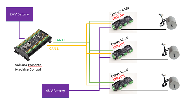
Below is a picture of my circuit :
I know that I forgot to disable some resistors for the communication on Odrive but I don’t understand why the CAN can’t be used now and why one card is damaged.
Before having other troubles with new Odrive. I need help to understand what caused these problems and if there is a way to check the integrity of the U1 chip.
Actually only one of them should be on, assuming the arduino has one too.
That is probably why it isn’t working. With four resistors in parallel, there is a total termination of 30 Ohm, which is too low. It should be 60 in total between CANH and CANL.
I am also one of the category “odrive killer”
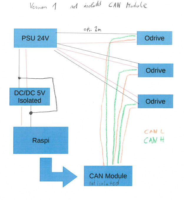
I had quite the same system setup as Nicagri but instead of the second battery i used an isolated DC/DC (for raspi and can module).
The same thing happen after some tests (10min drive) one of my odrive was dead. Micro controller get very hot and no communication (CAN/USB/DFU). Ok no problem, but in new one same thing happen second dead.
Now I am a little afraid because i don’t understand the root case of this issue.
In my opinion Nicagri has no ground loop in his system. ??
But theoretically CAN bus cant work because there is no common ground (the same in my system but for some reason it works)
Could CAN communication without common ground kill odrives?? or must be there an another root cause?
Second question would be:
My system consist of 3 odrives one is connected fixed to the system, the other two are connected by connectors and can be removed.
power plug (24V )
CAN (just CANH and CANL no gnd)
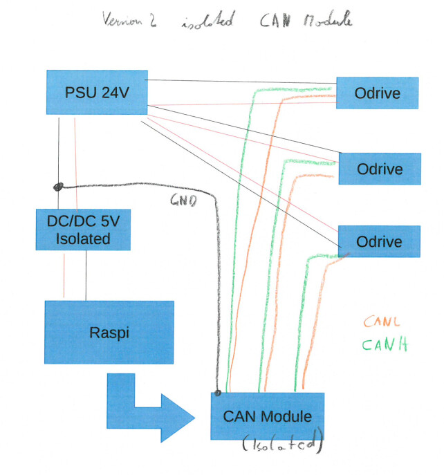
Now theoretically I need to short my PSU GND to the DC/DC GND (no more isolated ) to have one common ground, and CAN BUS is fine no Ground loop.
Other option would be a isolated CAN Driver and add to GND wire to the CAN connector to have a common gnd. But the GND on the odrive is not isolated so I have one extra ground wires to each odrive. Is there the risk for ground loop not higher in this case???
would be nice to get some ideas of the problem maybe from someone who never kill a odrive, if this kind of human exists
thx for the information.
But could you please check what would be the best solution. (i dont want to kill more odrives)
I had the system setup below without the ground connection between psu gnd and DC/DC ground.
For some reason CAN bus is working well but after some test odrive died. (could this be the reason for killing odrives?)
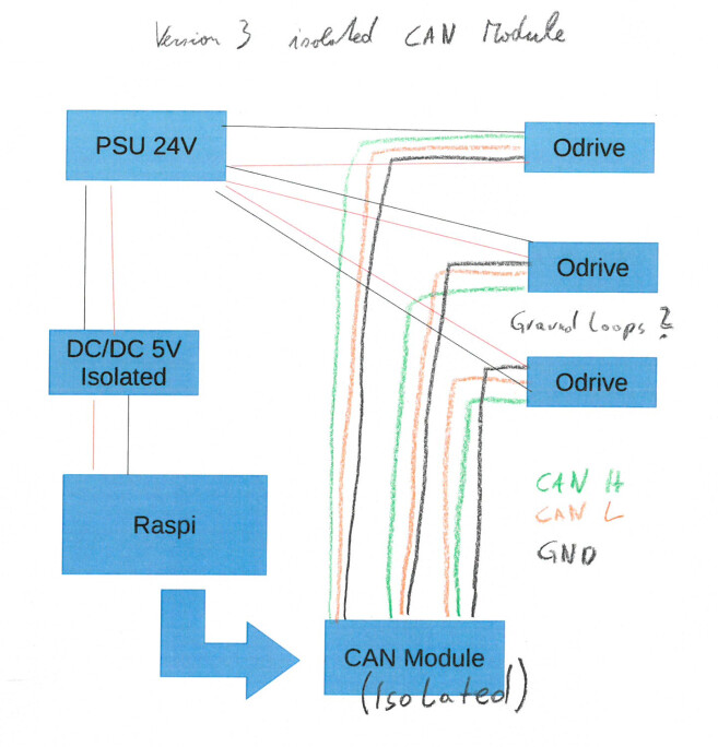
Or I use the wiring of the can bus Danfoss article but in my opinion i generate ground loops because the can module on the odrive is not isolate from the main GND
Is this right ??
Why are you shorting out the isolation of your dc/dc converter?
Also, both power and CAN should be wired in a bus configuration.
Take the power to the first ODrive, and from there to the next ODrive, and so on, and also twist the wires if you can. That reduces the overall length (resistance) and inductance of the cable, which ensures that there is minimal ground voltage difference between each ODrive. It is this ground voltage difference that causes them to die, because the logic wires signals start to carry current to equalise the ground voltages.
Do the same with CAN: wire CANH and CANL to the first ODrive (set the switch to No R) and from there to the next one (No R) and from there to the last one (CAN 120R). That way, the CAN is a linear bus with a termination at both ends - one in your CAN module and the other in the last ODrive.
Why are you shorting out the isolation of your dc/dc converter?
I created an unisolated system because the CAN module is also not isolated to have common gnd
(version 2 and 3 uses isolated CAN module)
Also, both power and CAN should be wired in a bus configuration.
I know what you mean but the system is a rover with one fixed odrive on the rover (shortest distance to pi and psu) the other two odrives are mounted on tools which are mounted on the rear and front of the rover and can be removed (plugs for CAN and DC)
So the system is variable either 1,2 or 3 odrives so bus configuration is a little  disadvantageous in point of electrical wiring.
(star configuration is easy one DC line to the front one to the back)
Do you think it really necessary to but everything in bus configuration
(6 x 200W BLDC motor need big wires)
But don’t know the solution
For me, I don’t understand the difference between an unisolated can transceiver (odrive gnd and CAN, same GND) and the isolated one with connected odrive GND?
For me it would be isolated if the CAN transceiver on odrive has and separate CAN GND
Or do I misunderstand something ?
You should try what Oskar suggested in that thread:
i.,e. move the ground connection point between the ODrives and the transceiver to somewhere other than the transceiver. Maybe connect them at the one permanent ODrive.
You are correct, an isolated interface does not connect GND, so it has two GND_A and GND_B which can be at different voltages.
So if for example GND_A is the ODrive GND and GND_B is the controller GND then there is no ground loop between the ODrive and the controller, but there is still a loop between ODrives because their transcievers are not individually isolated.
No, it should still work the way you have done it.
However, you need to be really careful with your connectors. Make sure that a) you always connect the power supply before the CAN bus. and b) you always connect GND before VBat. If you leave the CAN plugged in and you don’t have power connectors that are designed to connect the negative side first, then you could be in trouble.
Imagine that you had only the CAN connector plugged in for one of your ODrives: Only a small CAN wire links the ground to the battery, via the other ODrives.
Then, consider what happens if your connector were to connect the positive supply before the ground: Momentarily, the power return path would be the CAN cable.
Have you tried flashing firmware to any of your ‘dead’ ODrives? Sometimes they are only ‘soft-bricked’. For some reason, a current surge on the logic GND can erase the flash on the chip, but it is recoverable.
(But if the chips are getting hot, then it’s probably permaneltly damaged )