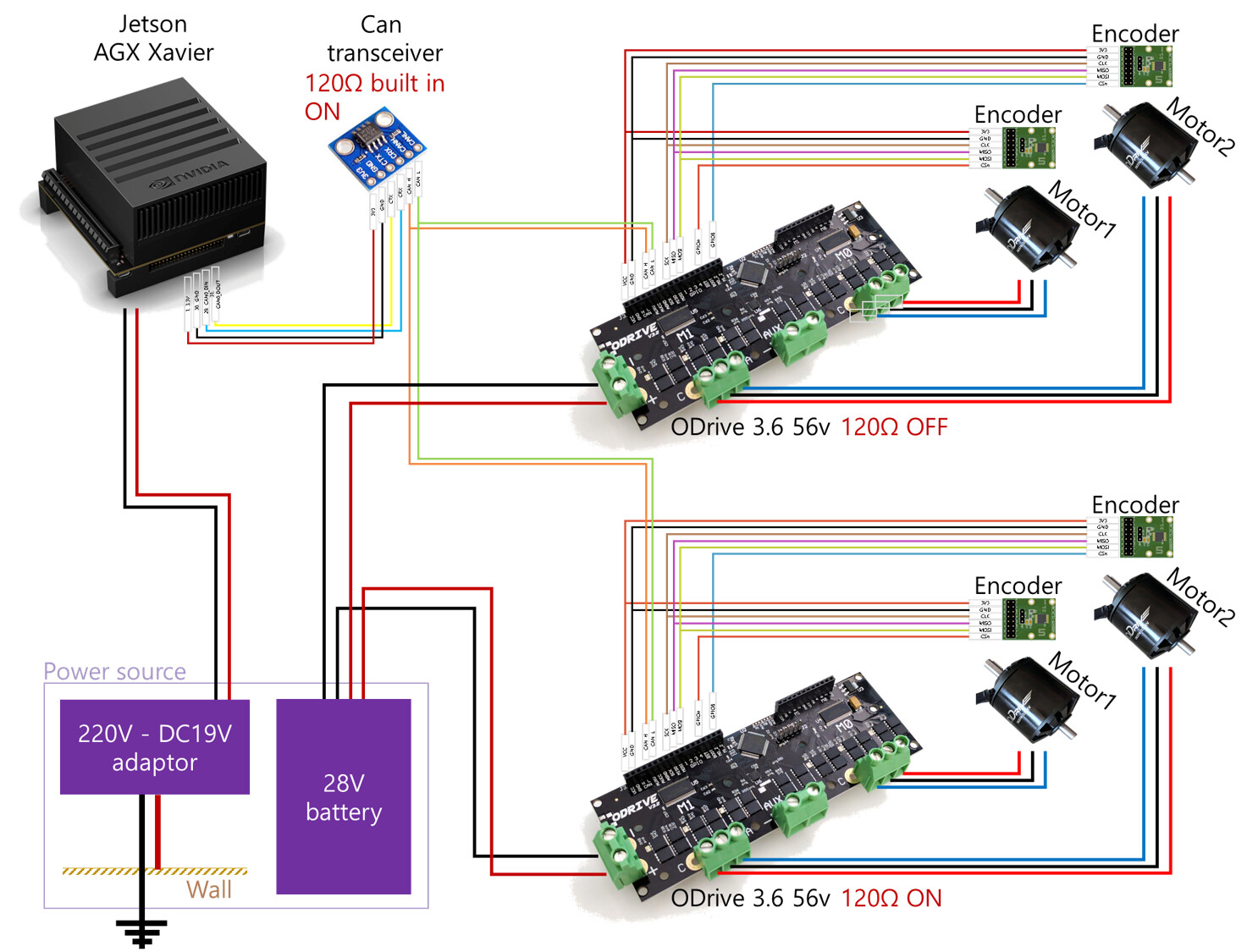
This is the wiring for entire my driving system with every single line.
I thing that cannot made a ground-loop so.
But it’s huge trouble maker now.
would you check this please?
thank you.
You can only do what you have done (connect only the CANH and CANL wires) IF you are using an isolated CAN transceiver. Non-isolated CAN is only able to cope with a difference of 4V or so between CANH/CANL and GND. So if there’s no ground reference, you’re in trouble.
If using a non-isolated transceiver you should connect the negative side of the battery to the negative of the power supply, and/or connect the GND of the ODrive to the GND of your transceiver. But if you use the isolated one I posted, it should work as you have drawn it.
That said, it shouldn’t have been so severe as to destroy the ODrive though, so I wonder if something else is going on… 
Are you using ferrites on the motors?
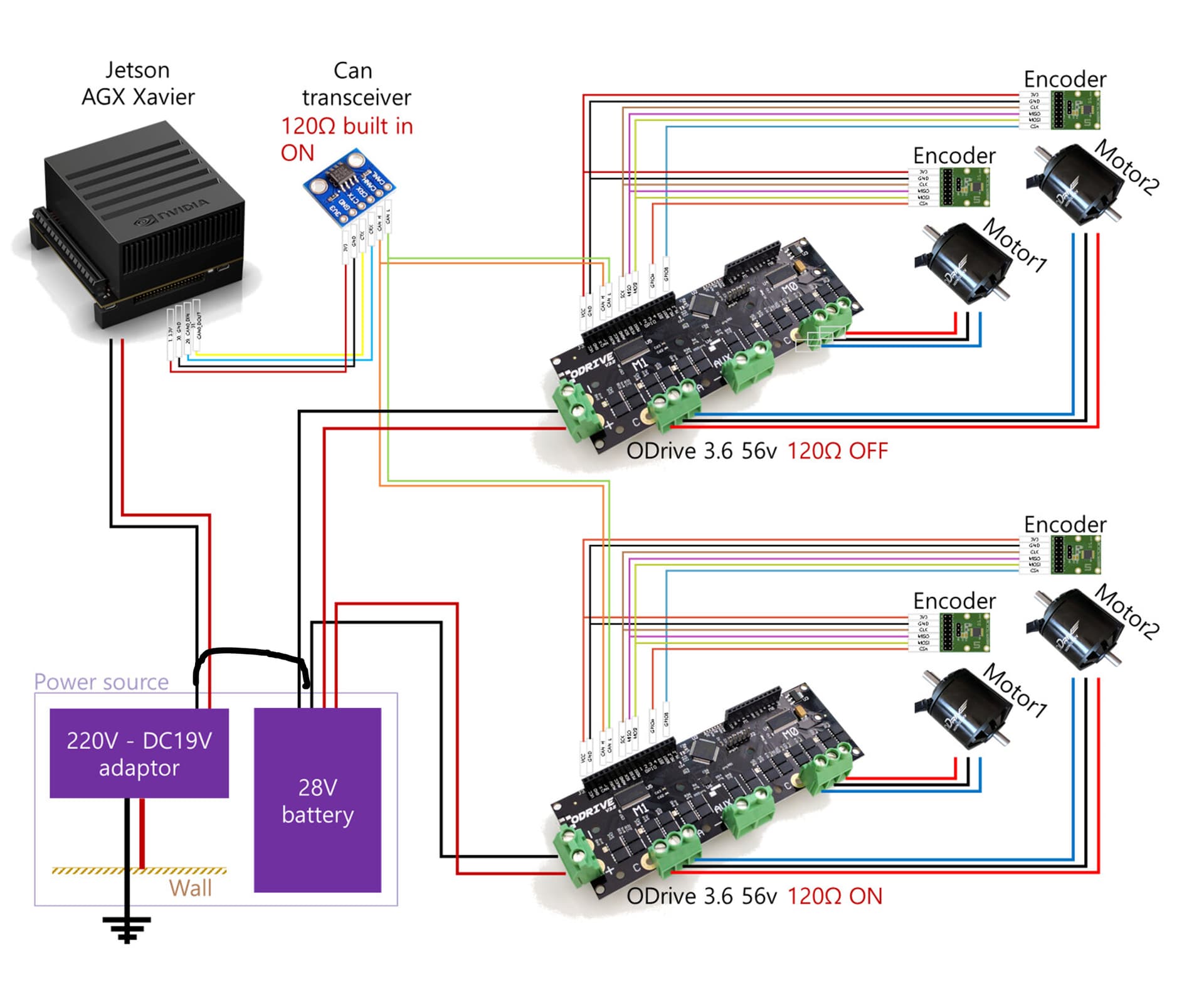
Thanks for making the fully annotated diagram, it is now clear what the problem is. You did a good job avoiding a ground loop, but you must still have a shared ground reference or you will get significant issues, as you have seen. My recommendation is to join the ground of the two halves of the system in a single point only to avoid loops. Like the blank link shown here:
I assumed here you are using the “KNACRO SN65HVD230 CAN Bus Module” that is in the guide you followed which is non-isolated. If you use an isolated CAN tranceiver, then your original wiring is correct.
Also I would strongly suggest to have power turned off when doing any wiring at all.
My guess is that only the U1 chip is broken, and you may be able to repair your ODrives by replacing just that chip. It is a SN65HVD232 also actually, so if you have some extra of those KNACRO boards you can try it quickly by taking one there. You can also order them online, check here and here.
3 Likes
Thank you for your kind reply. I will build and test the circuit, as your commentary. I’ll post again immediately after I’ve sorted out the things around. It’s great news about the ‘resurrection’. Two type of CAN chipset has been ordered right after read this. Thank you again and Have a good day!
1 Like
Thank you for the reply.
Actually I cannot understood whole things.
Thanks to you, I can confirm the grounding by looking at the documentation of the community dozens of times, and it seems that I have been able to understand the things that were not clear while studying the case of the community.
First, I will try to configure the circuit for isolated and non-isolated transceivers respectively.
I think it will work fine.
There is one more problem I’ve come across. It’s just that I wasn’t positing the concept of ground reference correctly.
Of the two power sources, The 19v thought that the terminal should not be grounded because I thought it was AC.
The problem was caused by increasing the motor speed or manipulating the encoder line and motor power line while the motor CAN communication was operating normally.
And, I’m sorry that I may have surprised you through the photos.
Actually, There are 5 Odrives lost in the process of performing CAN communication operation.
The rest of the Odrives have blown up for 8 months.
I hope you guys are’nt too surprised.
I am a beginner. So, I can’t figure out what caused the problem with odrive because of what I did. and
I can’t remember exactly one case at a time for the phenomenon.
I use toroids and ferrite cores for the motor, but I didn’t use them when trying the CAN connection in this attempt.
I was running 4 motors stably and well. And in this test, the ferrite core was omitted. The reason was my perception that the amount of current flowing through the motor was small.
I’ll build and test the circuit as you advised, then put it back together and post the diagram soon.
Thank you very much!
1 Like
The ferrite core doesn’t “care” about the current flowing through the motor (because the current in the three motor wires sum to zero and cancel out) - it is designed to dampen any very high frequency (MHz-GHz) currents that are flowing into and back out of the motor’s parasitic capacitance to Ground. It’s called a “common mode choke” - look it up 
With nothing to dampen these oscillations, I suppose the only thing tying the board to ground potential was the poor CAN bus transceiver. 
Thanks for your help.
I will look into more about common mode chokes.
Now I am going to wire the system as shown.
Please let me know if this will work.
The CAN transceiver in this system will be replaced by another isolated one.

Looks fine, except that (the way you have drawn it) the ground path between the two ODrives looks quite long.
I would advise to keep it as short as you can (which is why I suggested wiring them as a ‘bus’ earlier) i.e. take two wires to the first ODrive, and take two more wires from the first ODrive to the second ODrive.
Also, don’t forget that these wires need to be kept together as a pair - ideally, twist them if you have a vice and an electric drill handy. (stretch the wire before you release it to retain its twisted shape)
Yes this looks good.
Hi towen, madcowswe.
Thanks to you guys.
I’m trying to go there and I’ve encountered a situation that"2 more odrives"
I think that The bad Transceiver is Guilty.
I have to wait till to get The part you recommend and more odrives
I think almost there.
Thank you again.
Wtf? You blew another two? 
There is something seriously wrong with what you are doing, but I don’t know what it is… 
Maybe some pictures of your setup will help
1 Like
Thanks for your concern.
I’ve made success by your advise in test system actually.
It was perfect and controllable.
system and protocol are fine.
After then, I’ve Tried to apply for real system.
But the real system has a difference about power diagram.
It contains 5v inverter from 24v battery.
Absolutely I’ve made an earth for its negative line.
I thought that will not be bad but in vain.
So, I think that the bad transceiver not isolated thing is the only factor for this situation.
Fortunately, the Isolated thing that you recommended has been delivered yesterday.
I have only 1 odrive now that couldn’t be a scream goat.
So I’m waiting Odrives for redundancy now.
Everything will be fine.
If my disaster will not have ending, I’ll ask here for that.
I really appreciate your help.
1 Like
It’s arrived yesterday!!
Your answer helped me a lot.
Is there a problem if i use an isolated transceiver with shared ground reference?
An isolated transceiver will have two different ground references. One for the bus side and another for the device side.
It is correct to connect the ODrive ground to the bus-side GND of the transceiver - but if it is isolated, then that will not be connected to the USB ground.
It’s fine to connect the two grounds together on the isolated CAN transceiver.
- If you connect the grounds at a far away star point, then the isolation helps break the ground loop. This should work well.
- If you connect the grounds right by the transceiver it basically becomes a regular non-isolated transceiver, and then those rules apply.
1 Like
It worked!!!
Odrive forever!!!
all thanks to you and madcow!
2 Likes
I really appreciate everything you’ve done!!
2 Likes
To everyone working with ODrive and Jetson: Could you please summarize the main issue you encountered and how you fixed it?
The main issue we see is the fact that NVIDIA JetPack 6 doesn’t have support for the drivers needed for the USB-CAN adapter, see here. Other than that, there’s not much difference between getting CAN running on a Jetson and on another Linux system. Some of the Jetsons have pins to use a CAN transceiver directly, instead of needing a USB-CAN adapter, which makes things easier.