CAN comms with ESP32 and S1 not working

Attempting to get an ODrive S1 to work/communicate with an ESP32 using CAN bus communications and Waveshare SN65HVD230 CAN Board, driving a 6" hoverboard motor that has the typical low-resolution (~4 degree) Hall position sensors.

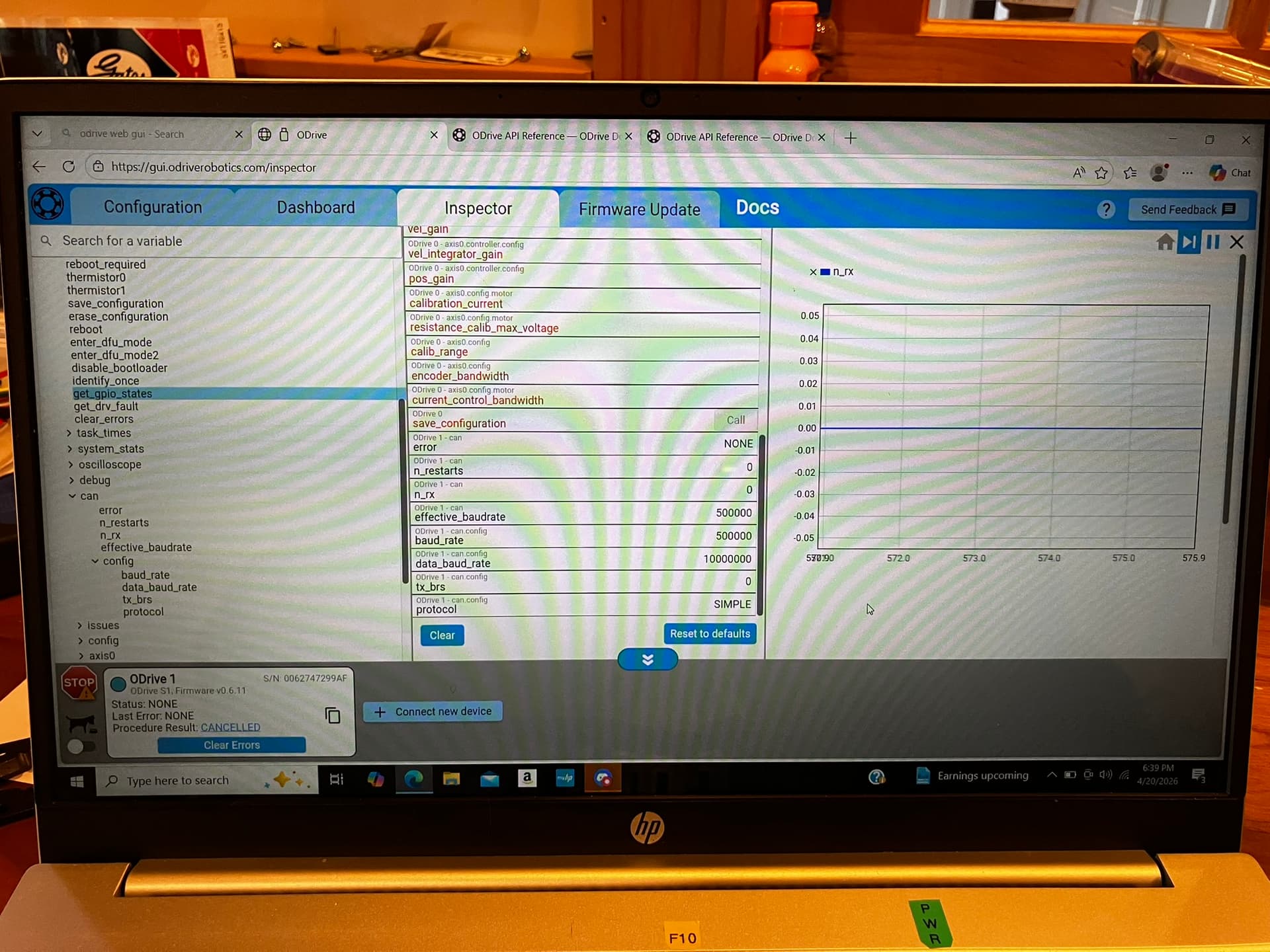
I have used the web GUI to configure the S1 for the hoverboard motor. I can put the hoverboard motor through its paces using the web GUI; position control, velocity control and torque control all work fine. I have saved the settings to the S1. I have also been successful in controlling the motor/controller using the ODriveUART.h and serial commands sent from the ESP32 to the S1. I am planning on having multiple BLDC motors in this project, so I want to convert the control method to CAN bus.

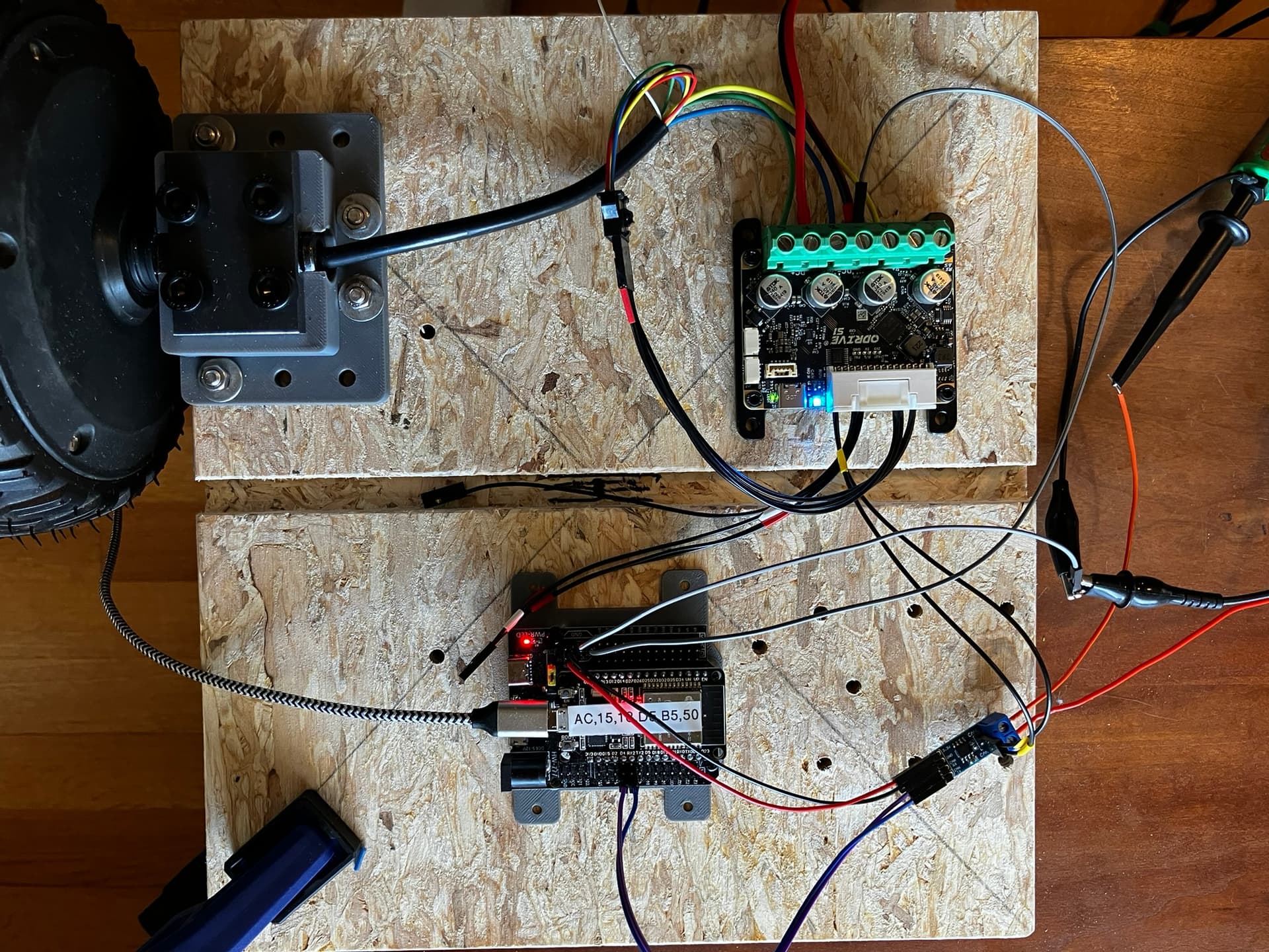
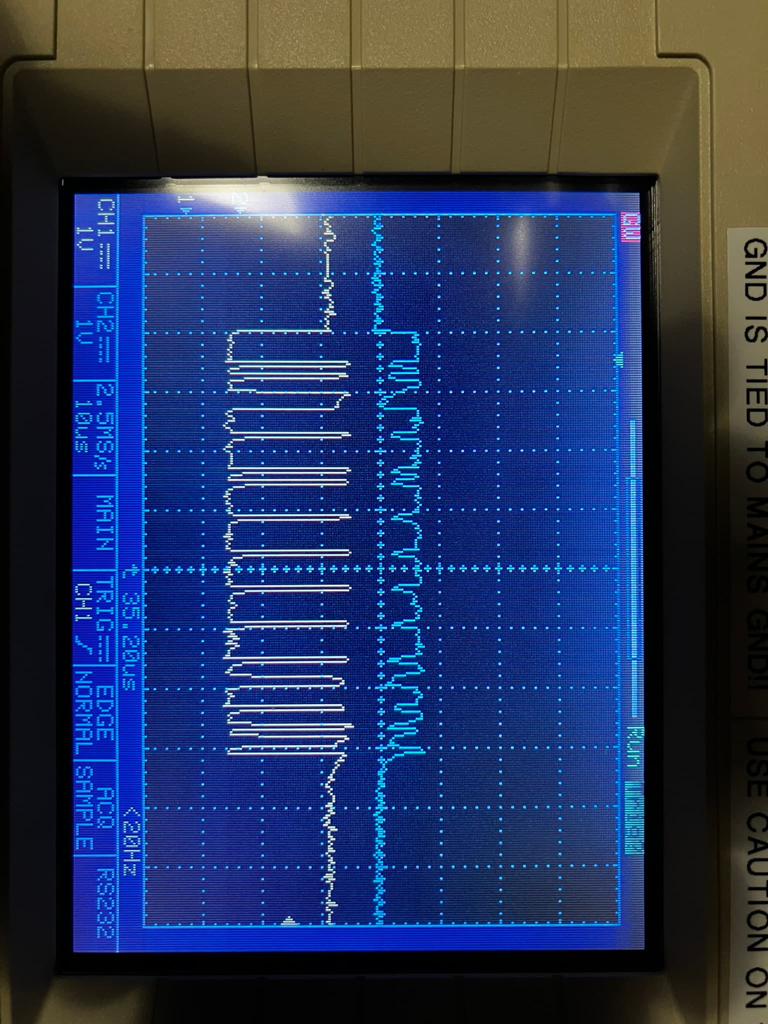
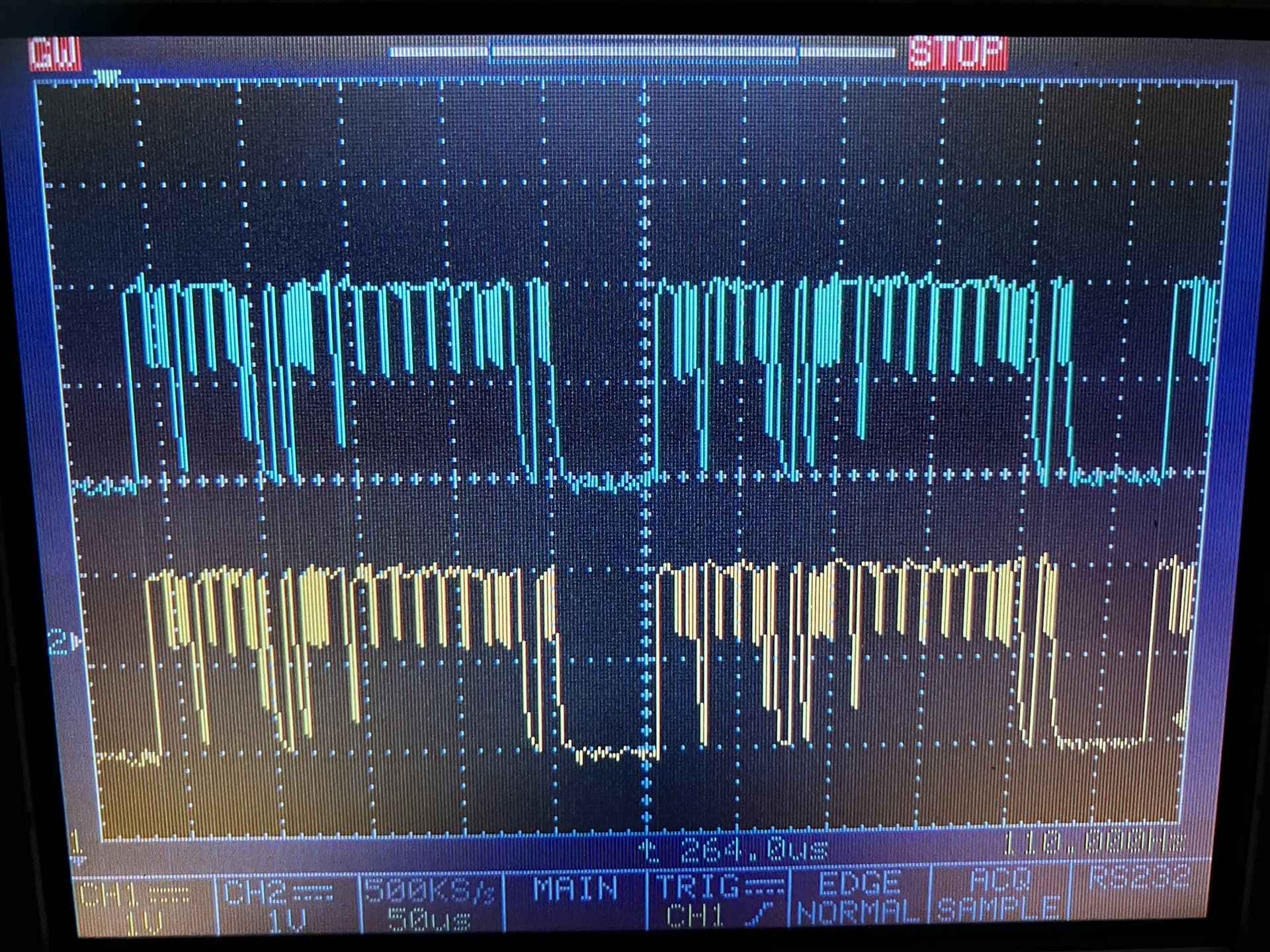
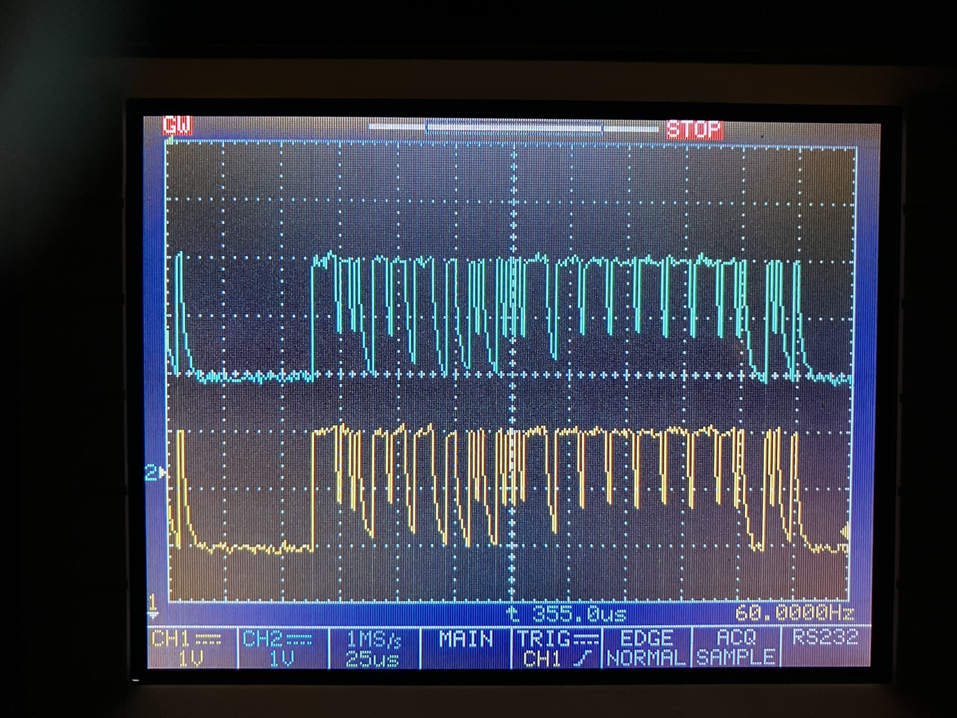
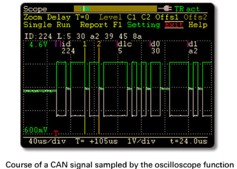
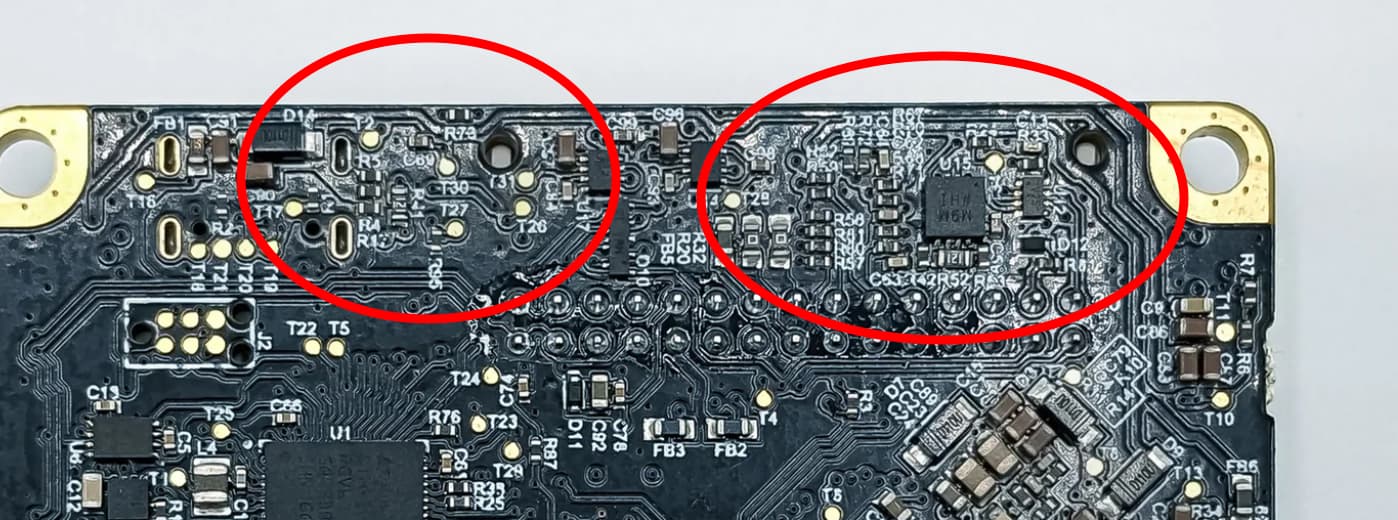
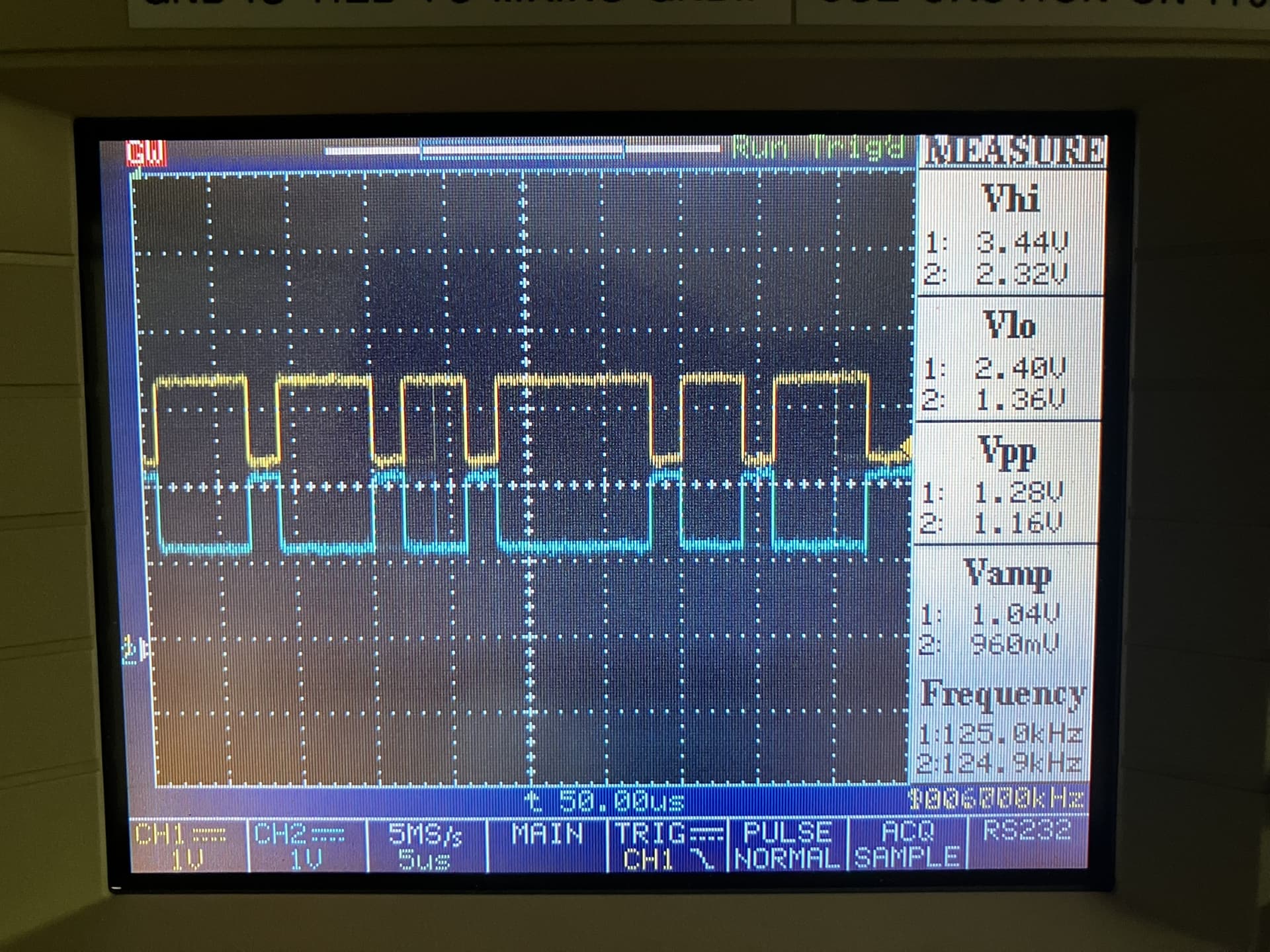
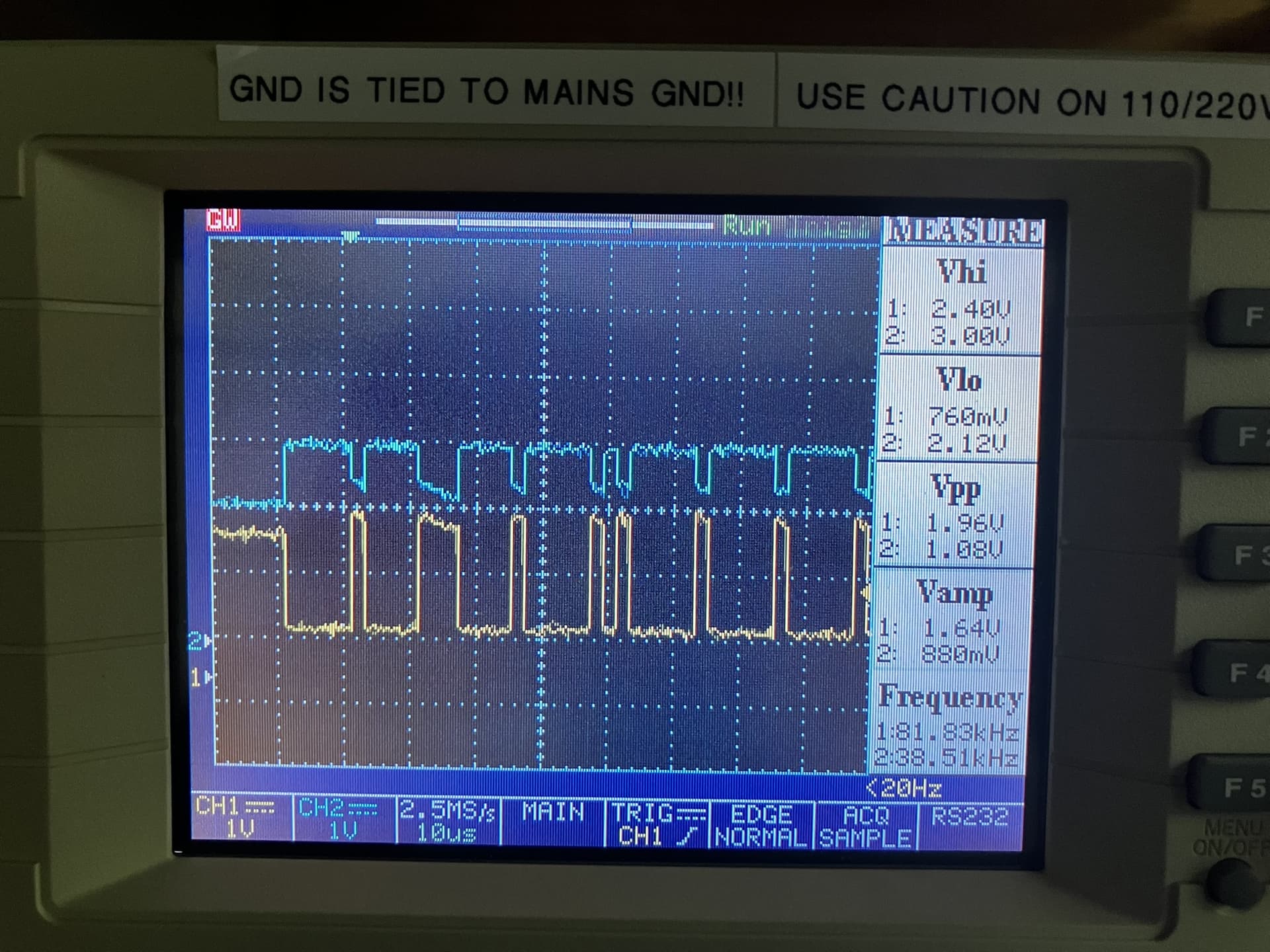
I connected the ESP32 to the Waveshare SN65HVD230 (3.3v, Gnd, TX, Rx), the SN65HVD230 to the S1 (CANH, CANL) and connected a common ground (hoverboard battery negative terminal to a ESP32 Gnd pin). Switch on S1 is set to 120 ohm resistor and the bus shows a correct 60 ohms between the CANh and CANL. I also have an o’scope attached to the CAN bus and it shows what I believe is a successful transmission of a command from the ESP32 to the CAN bus.

I have used the attached program to attempt to get the controller into AXIS_STATE_CLOSED_LOOP_CONTROL, and even though I see the command go over the CAN bus with the o’scope, the controller LED remains a slow pulsing blue (which I believe means ‘idle state, awaiting command’). I’m thinking the LED should go to the green color, because the is what happens when I set the state to AXIS_STATE_CLOSED_LOOP_CONTROL on the web GUI.

I have also tried sending the command AXIS_STATE_FULL_CALIBRATION_SEQUENCE using the same program (simply changing the message byte[0] to 0x03), but there is no reaction from the motor/controller.

I’m attaching the program I am running on the ESP32 and pictures of the wiring setup as well as the o’scope signal capture of what I believe is a correct signals over the CAN bus. I am attaching the CAN bus to pins 1 and 2 of the large pinheader of the S1 which I believe is correct.

I have tried using different baudrates for the CAN bus (I set to 500K using the web GUI), tried 250K, 500K and 1M in the attached program but still no reaction from the S1.

I have also tried different node ID’s (0 and 1) using the web GUI and changing the attached program, but still no reaction from the S1.

Lastly, I have two S1s on hand, I have tried both units but neither works with the CAN bus after working well with the web GUI and also ESP32 UART.

I am stumped, does anyone have any ideas???

Nate

// Documentation for this example can be found here:
// https://docs.odriverobotics.com/v/latest/guides/arduino-uart-guide.html

// 0: AXIS_STATE_UNDEFINED – The state is unknown or the ODrive is not communicating.
// 1: AXIS_STATE_IDLE – The axis is inactive; no power is sent to the motor.
// 2: AXIS_STATE_STARTUP_SEQUENCE – The axis is performing its initial startup routine.
// 3: AXIS_STATE_FULL_CALIBRATION_SEQUENCE – Performs both motor and encoder calibration.
// 4: AXIS_STATE_MOTOR_CALIBRATION – Measures motor resistance and inductance.
// 6: AXIS_STATE_ENCODER_INDEX_SEARCH – Finds the physical index pulse on an encoder.
// 7: AXIS_STATE_ENCODER_OFFSET_CALIBRATION – Calibrates the relationship between the encoder and motor phases.
// 8: AXIS_STATE_CLOSED_LOOP_CONTROL – The motor is actively holding position or following a velocity/torque command.
// 9: AXIS_STATE_LOCKIN_SPIN – Rotates the motor at a fixed speed without using encoder feedback (open loop).
// 10: AXIS_STATE_ENCODER_DIR_FIND – Automatically determines the direction of the encoder.
// 11: AXIS_STATE_HOMING – Moves the axis until it hits an endstop to find a home position.
// 12: AXIS_STATE_ENCODER_HALL_POLARITY_CALIBRATION – Specifically for motors using Hall effect sensors


#include "driver/twai.h"

// Define CAN pins
#define CAN_TX GPIO_NUM_17
#define CAN_RX GPIO_NUM_16


#define ODRIVE_NODE_ID              0x00

#define SET_AXIS_STATE_CMD          0x07

#define AXIS_STATE_CLOSED_LOOP      0x08
#define FULL_CALIBRATION_SEQUENCE   0x03


// SETUP  --  SETUP  --  SETUP  --  SETUP  --  SETUP  --  SETUP  --  SETUP  --  SETUP  --  SETUP  --  SETUP  --  SETUP  --  SETUP  --  
// SETUP  --  SETUP  --  SETUP  --  SETUP  --  SETUP  --  SETUP  --  SETUP  --  SETUP  --  SETUP  --  SETUP  --  SETUP  --  SETUP  --
void setup()        {
  Serial.begin(115200);
  delay(2000);
  Serial.print("Starting odriveCanTest");
  
  // Initialize configuration structures
  twai_general_config_t g_config = TWAI_GENERAL_CONFIG_DEFAULT(CAN_TX, CAN_RX, TWAI_MODE_NORMAL);
  twai_timing_config_t t_config = TWAI_TIMING_CONFIG_500KBITS();
  twai_filter_config_t f_config = TWAI_FILTER_CONFIG_ACCEPT_ALL();

  // Install and start CAN driver
  if (twai_driver_install(&g_config, &t_config, &f_config) == ESP_OK) {
    Serial.println("Driver installed");
  } else {
    Serial.println("Failed to install driver");
    return;
  }
  
  if (twai_start() == ESP_OK) {
    Serial.println("twai CAN Driver started");
  }

}
// SETUP  --  SETUP  --  SETUP  --  SETUP  --  SETUP  --  SETUP  --  SETUP  --  SETUP  --  SETUP  --  SETUP  --  SETUP  --  SETUP  --  
// SETUP  --  SETUP  --  SETUP  --  SETUP  --  SETUP  --  SETUP  --  SETUP  --  SETUP  --  SETUP  --  SETUP  --  SETUP  --  SETUP  --


// MAIN --  MAIN --  MAIN --  MAIN --  MAIN --  MAIN --  MAIN --  MAIN --  MAIN --  MAIN --  MAIN --  MAIN --  MAIN --  MAIN --  
void loop()  {  
  // Header
  twai_message_t message;
  message.identifier = ((ODRIVE_NODE_ID << 5) | SET_AXIS_STATE_CMD);
  message.extd = 0; 
  message.data_length_code = 4;
  
  // Data
  message.data[0] = AXIS_STATE_CLOSED_LOOP;
  message.data[1] = 0x00;
  message.data[2] = 0x00;
  message.data[3] = 0x00;

  // Send Message
  if (twai_transmit(&message, pdMS_TO_TICKS(1000)) == ESP_OK) {
    Serial.println("CAN message sent");
  } else {
      Serial.println("Failed to send message");
  }


  delay(5000); 
  
}
// MAIN --  MAIN --  MAIN --  MAIN --  MAIN --  MAIN --  MAIN --  MAIN --  MAIN --  MAIN --  MAIN --  MAIN --  MAIN --  MAIN --  


Thanks for all the detailed info!

The wiring and everything looks fine.

On the web GUI, could you check can.n_rx and see if it’s increasing when you send the CAN message?

Also, note we have ESP32 support in our Arduino example, that might be good to give a quick try just in case there’s some subtle endianness issue here: GitHub - odriverobotics/ODriveArduino: Arduino library for the ODrive · GitHub

Hello and thank you for the response!

Attached is a photo of the web GUI Inspector page which is open while I am running the S1 and having the ESP32 run the previously posted program that sends the SET_AXIS_STATE_CMD command with AXIS_STATE_CLOSED_LOOP in the data field. It is consistently showing 0 as the can.n_rx which I would guess indicates that the messages from the ESP32 are not getting through, or for some reason the S1 is not acknowledging.

Another possible clue to this problem (or maybe more confusion) is that if I go back into the Configuration tab on the web GUI and turn on a cyclic message (I ticked “Bus Voltage & Current” to be sent every 1000ms) I can see a lot of data on the CAN bus with the o’scope (I previously had NO cyclic messages enabled from the S1 to allow me to clearly see only the data that the ESP32 was putting on the CAN bus). The thing is, the data on the bus from the S1 is WAY more often than once per 1000ms, it seems to be like every 250us. O’scope picture attached. ALSO, the signals are not differential, both CANL and CANH seem to be the same voltage, which is really odd, because I’m pretty sure CAN bus is supposed to be differential signals. Yes, probes are indeed attached to the opposite CANH/CANL wires of the bus, not on the same wire. What the heck?!?! So it seems like activating the cyclic message from the S1 sends a signal that is not differential and not at the specified 1000ms intervals?

Cyclic signal from S1, 50us per division:

Cyclic signal from S1, 25us per division:

Anyhow, I will try the program from the ODrive Arduino example and post my results tomorrow morning, Thank you for taking a look at this!!

Nate

Hmm, that’s definitely quite interesting. Yes, it should be differential.

The S1 may be retrying if it’s not detecting the message sent properly, but it should also be throwing an error. Baudrate looks correct, at least per the scope.

Should look more something like this.e
image

Your original image from the ESP32 also doesn’t look quite how it should – the CH1 looks more or less correct, but the magnitude of CH2 is way too small:

I’d do a quick test – if you disconnect the CAN connection between the S1 and ESP32, what does (1) the CAN output from ESP32 look like, and (2) what does the CAN output from the S1 look like (with the cyclic messages enabled)? I’m curious if something is forcing the bus lines together, or if a transceiver is bad/damaged. It may be worth pulling the S1 from the heatspreader and checking for any conductive debris or components that seem damaged – feel free to send some pics of the board around these areas:

, as well as just general pics of the top/bottom.

Thank you for all the excellent info. When I disconnected the S1 from the ESP32/transceiver to inspect the bottom side, I noticed when I moved the S1 the CAN bus signal changed back and forth from the jagged signal I posted earlier to a normal square-edged signal. After a lot of fiddling, I found the issue was that the female socket of pin #1 of the JST-PUD header was making intermittent contact. I preformed corrective micro-surgery on the socket and then started getting an excellent CAN signal from the S1:

I then observed the signal from the ESP32/SN65HVD230 while only connected to the 120 ohm terminating resistor and it was still very lopsided:

After a bunch of internet research, I am still somewhat unsure if this is a feature of the TI SN65HVD230 or the result of a Chinese clone (makings on chip look genuine, but who knows). I have ordered what I hope to be some genuine SN65HVD230’s from Digikey to test and see if there is a difference.

In any case, I pushed along and re-connected the S1 ↔ SN65HVD230 ↔ ESP32 and tested the setup using the code at the ODrive Github Arduino repo you posted… IT WORKS!! The bare-bones test code I posted in the beginning of this thread also works.

Net learnings: The root failure was poor connection at the JST-PUD header. The SN65HVD230 produces strange (although maybe not out of spec) signals on the CAN bus. An O’scope is critical in diagnosing CAN bus issues.

Thank you very much for your help!!
Nate

Wow, I’m glad to hear you found the root cause!! That totally explains the “single ended” signal – if the S1 was trying to assert the high line, and the low was left floating/disconnected, then it will drift to follow high.

After a bunch of internet research, I am still somewhat unsure if this is a feature of the TI SN65HVD230 or the result of a Chinese clone (makings on chip look genuine, but who knows). I have ordered what I hope to be some genuine SN65HVD230’s from Digikey to test and see if there is a difference.

Actually I’ll have to take back what I said yesterday, with a bit of further thinking I’m pretty sure the wonky/lopsided CAN signals are just fine, I just forgot that the 65HVD230 is a 3.3V CAN transceiver! Typically with CAN, the recessive common-mode voltage is 2.5V, and the asserted voltages for CANH and CANL are 3.5-4V and 1-1.5V (ish) respectively. But the actual thing that’s checked is the differential voltage between CANH and CANL – 0.5V or lower is recessive, 0.9V or higher is asserted (but the more the better, for noise immunity) .

So if you have a 3.3V-supply CAN transceiver, it can’t pull CANH to 3.5V, and given supply voltage variation and transistor headroom, you have a worst-case drive voltage of maybe ~2.8-2.9V to work with. So if you can only guarantee you can drive CANH to 2.9V (as opposed to ~4V) when asserting the bus, you need to make up for that >0.9V voltage difference with CANL, by driving it way down.

You can see this when comparing a generic 5V CAN transceiver IC with the SN65HVD230:

MCP2562 (common/generic 5V CAN transceiver):

SN65HVD230:

So it looks like the SN65HVD230 drives the CANH/CANL differential voltage to 2V, just like the MCP2562, but it does so pretty asymmetrically, which is exactly what we’re seeing here. This is, per the CAN spec, 100% valid and should be cross-compatible between both transceivers – it just totally threw me off because I don’t typically work with those 3.3V transceivers, so I wasn’t expecting the asymmetric waveform. Sorry for the false alarm!

That is a great explanation of the lopsided signal from the SN65HVD230!!

I had referenced the data sheet for that device but still wasn’t quite sure what the expected signal levels were because some of the terminology they were using is unique to CAN bus and new to me. I was kind of “huh?” when it was talking about “dominant” and “recessive” parameters, I would think “active/floating” or maybe even “high/low” might be more intuitive (actually “high/low” is a silly suggestion, as it would cause confusion depending on whether CANH or CANL was being referenced), but I guess that is defined in the CAN bus specification wherever that is.

And that’s why I said “maybe not out of spec” as it is sending a differential signal. But anyhow, definitely a leaning experience and I appreciate your knowledgeable input!

Nate

I was kind of “huh?” when it was talking about “dominant” and “recessive” parameters

Agreed! “logic 1” vs “logic 0” may be easier. But also there’s some interesting stuff with how CAN does anti-collision / arbitration that makes sense for that to be the terminology. I personally prefer “asserted” / “recessive” or “asserted” / “released”, it makes more sense for me, but it’s not “proper” terminology.