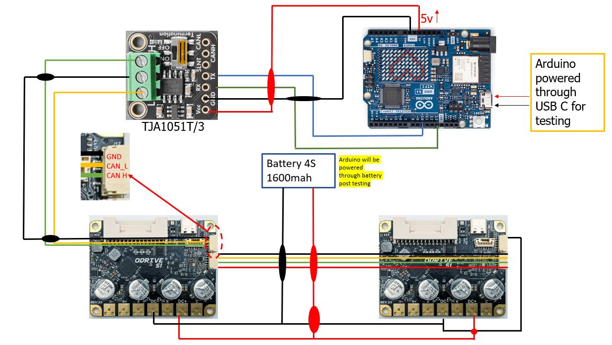
I am trying to build a self-balancing robot using two ODrive S1s,BGM5208-200-12 gimbal motors; using onboard encoders, Arduino Uno R4 WiFi, TJA051T/3 CAN transceiver and MPU6050 (not shown here). My circuit diagram is below.
To begin testing, I made all the connections according to the circuit diagram, except for the daisy chain part, so I initially used only one ODrive with node ID 0. Everything worked as expected with the “Sinewave CAN” example code. Then, I disconnected the ODrive with node ID 0, modified the code to change the node ID to 1, and connected the second ODrive (node ID 1). This setup worked as expected. So both odrives 0 and 1 work independently.
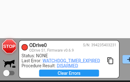
One observation I made is that when using the default example to run a single ODrive with node id 0; code hangs at “waiting for odrive” if I daisy chain second odrive with node 1. Is this how it is supposed to work?
However, when I modified the code to include a second ODrive with node ID 1 and tried to run both ODrives simultaneously, the code hangs at “waiting for ODrive.” and nothing works. Below is the modified code.
#include <Arduino.h>
#include "ODriveCAN.h"

// Documentation for this example can be found here:
// https://docs.odriverobotics.com/v/latest/guides/arduino-can-guide.html


/* Configuration of example sketch -------------------------------------------*/

// CAN bus baudrate. Make sure this matches for every device on the bus
#define CAN_BAUDRATE 1000000

// ODrive node_id for odrv0
#define ODRV0_NODE_ID 0
#define ODRV1_NODE_ID 1

// Uncomment below the line that corresponds to your hardware.
// See also "Board-specific settings" to adapt the details for your hardware setup.

// #define IS_TEENSY_BUILTIN // Teensy boards with built-in CAN interface (e.g. Teensy 4.1). See below to select which interface to use.
#define IS_ARDUINO_BUILTIN // Arduino boards with built-in CAN interface (e.g. Arduino Uno R4 Minima)
// #define IS_MCP2515 // Any board with external MCP2515 based extension module. See below to configure the module.


/* Board-specific includes ---------------------------------------------------*/

#if defined(IS_TEENSY_BUILTIN) + defined(IS_ARDUINO_BUILTIN) + defined(IS_MCP2515) != 1
#warning "Select exactly one hardware option at the top of this file."

#if CAN_HOWMANY > 0 || CANFD_HOWMANY > 0
#define IS_ARDUINO_BUILTIN
#warning "guessing that this uses HardwareCAN"
#else
#error "cannot guess hardware version"
#endif

#endif

#ifdef IS_ARDUINO_BUILTIN
// See https://github.com/arduino/ArduinoCore-API/blob/master/api/HardwareCAN.h
// and https://github.com/arduino/ArduinoCore-renesas/tree/main/libraries/Arduino_CAN

#include <Arduino_CAN.h>
#include <ODriveHardwareCAN.hpp>
#endif // IS_ARDUINO_BUILTIN

#ifdef IS_MCP2515
// See https://github.com/sandeepmistry/arduino-CAN/
#include "MCP2515.h"
#include "ODriveMCPCAN.hpp"
#endif //

#ifdef IS_TEENSY_BUILTIN
// See https://github.com/tonton81/FlexCAN_T4
// clone https://github.com/tonton81/FlexCAN_T4.git into /src
#include <FlexCAN_T4.h>
#include "ODriveFlexCAN.hpp"
struct ODriveStatus; // hack to prevent teensy compile error
#endif // IS_TEENSY_BUILTIN


/* Board-specific settings ---------------------------------------------------*/


/* Teensy */

#ifdef IS_TEENSY_BUILTIN

FlexCAN_T4<CAN1, RX_SIZE_256, TX_SIZE_16> can_intf;

bool setupCan() {
  can_intf.begin();
  can_intf.setBaudRate(CAN_BAUDRATE);
  can_intf.setMaxMB(16);
  can_intf.enableFIFO();
  can_intf.enableFIFOInterrupt();
  can_intf.onReceive(onCanMessage);
  return true;
}

#endif // IS_TEENSY_BUILTIN


/* MCP2515-based extension modules -*/

#ifdef IS_MCP2515

MCP2515Class& can_intf = CAN;

// chip select pin used for the MCP2515
#define MCP2515_CS 10

// interrupt pin used for the MCP2515
// NOTE: not all Arduino pins are interruptable, check the documentation for your board!
#define MCP2515_INT 2

// freqeuncy of the crystal oscillator on the MCP2515 breakout board.
// common values are: 16 MHz, 12 MHz, 8 MHz
#define MCP2515_CLK_HZ 8000000


static inline void receiveCallback(int packet_size) {
  if (packet_size > 8) {
    return; // not supported
  }
  CanMsg msg = {.id = (unsigned int)CAN.packetId(), .len = (uint8_t)packet_size};
  CAN.readBytes(msg.buffer, packet_size);
  onCanMessage(msg);
}

bool setupCan() {
  // configure and initialize the CAN bus interface
  CAN.setPins(MCP2515_CS, MCP2515_INT);
  CAN.setClockFrequency(MCP2515_CLK_HZ);
  if (!CAN.begin(CAN_BAUDRATE)) {
    return false;
  }

  CAN.onReceive(receiveCallback);
  return true;
}

#endif // IS_MCP2515


/* Arduinos with built-in CAN */

#ifdef IS_ARDUINO_BUILTIN

HardwareCAN& can_intf = CAN;

bool setupCan() {
  return can_intf.begin((CanBitRate)CAN_BAUDRATE);
}

#endif


/* Example sketch ------------------------------------------------------------*/

// Instantiate ODrive objects
ODriveCAN odrv0(wrap_can_intf(can_intf), ODRV0_NODE_ID);
ODriveCAN odrv1(wrap_can_intf(can_intf), ODRV1_NODE_ID);// Standard CAN message ID
ODriveCAN* odrives[] = {&odrv0, &odrv1}; // Make sure all ODriveCAN instances are accounted for here

struct ODriveUserData {
  Heartbeat_msg_t last_heartbeat;
  bool received_heartbeat = false;
  Get_Encoder_Estimates_msg_t last_feedback;
  bool received_feedback = false;
};

// Keep some application-specific user data for every ODrive.
ODriveUserData odrv0_user_data;
ODriveUserData odrv1_user_data;

// Called every time a Heartbeat message arrives from the ODrive
void onHeartbeat(Heartbeat_msg_t& msg, void* user_data) {
  ODriveUserData* odrv_user_data = static_cast<ODriveUserData*>(user_data);
  odrv_user_data->last_heartbeat = msg;
  odrv_user_data->received_heartbeat = true;
}

// Called every time a feedback message arrives from the ODrive
void onFeedback(Get_Encoder_Estimates_msg_t& msg, void* user_data) {
  ODriveUserData* odrv_user_data = static_cast<ODriveUserData*>(user_data);
  odrv_user_data->last_feedback = msg;
  odrv_user_data->received_feedback = true;
}

// Called for every message that arrives on the CAN bus
void onCanMessage(const CanMsg& msg) {
  for (auto odrive: odrives) {
    onReceive(msg, *odrive);
  }
}

void setup() {
  Serial.begin(115200);

  // Wait for up to 3 seconds for the serial port to be opened on the PC side.
  // If no PC connects, continue anyway.
  for (int i = 0; i < 30 && !Serial; ++i) {
    delay(100);
  }
  delay(200);


  Serial.println("Starting ODriveCAN demo");

  // Register callbacks for the heartbeat and encoder feedback messages
  odrv0.onFeedback(onFeedback, &odrv0_user_data);
  odrv0.onStatus(onHeartbeat, &odrv0_user_data);

  odrv1.onFeedback(onFeedback, &odrv1_user_data);
  odrv1.onStatus(onHeartbeat, &odrv1_user_data);

  // Configure and initialize the CAN bus interface. This function depends on
  // your hardware and the CAN stack that you're using.
  if (!setupCan()) {
    Serial.println("CAN failed to initialize: reset required");
    while (true); // spin indefinitely
  }

  Serial.println("Waiting for ODrive0...");
  while (!odrv0_user_data.received_heartbeat) {
    pumpEvents(can_intf);
    delay(100);
  }

  Serial.println("found ODrive0");

  Serial.println("Waiting for ODrive1...");
  while (!odrv1_user_data.received_heartbeat) {
    pumpEvents(can_intf);
    delay(100);
  }

  Serial.println("found ODrive1");

  // request bus voltage and current (1sec timeout)
  Serial.println("attempting to read bus voltage and current");
  Get_Bus_Voltage_Current_msg_t vbus;
  if (!odrv0.request(vbus, 1)) {
    Serial.println("vbus request failed!");
    while (true); // spin indefinitely
  }

  Serial.print("DC voltage [V]: ");
  Serial.println(vbus.Bus_Voltage);
  Serial.print("DC current [A]: ");
  Serial.println(vbus.Bus_Current);

  Serial.println("Enabling closed loop control on Odrive0...");
  while (odrv0_user_data.last_heartbeat.Axis_State != ODriveAxisState::AXIS_STATE_CLOSED_LOOP_CONTROL) {
    odrv0.clearErrors();
    delay(1);
    odrv0.setState(ODriveAxisState::AXIS_STATE_CLOSED_LOOP_CONTROL);

    // Pump events for 150ms. This delay is needed for two reasons;
    // 1. If there is an error condition, such as missing DC power, the ODrive might
    //    briefly attempt to enter CLOSED_LOOP_CONTROL state, so we can't rely
    //    on the first heartbeat response, so we want to receive at least two
    //    heartbeats (100ms default interval).
    // 2. If the bus is congested, the setState command won't get through
    //    immediately but can be delayed.
    for (int i = 0; i < 15; ++i) {
      delay(10);
      pumpEvents(can_intf);
    }
  }

  Serial.println("Enabling closed loop control on Odrive1...");
  while (odrv1_user_data.last_heartbeat.Axis_State != ODriveAxisState::AXIS_STATE_CLOSED_LOOP_CONTROL) {
    odrv1.clearErrors();
    delay(1);
    odrv1.setState(ODriveAxisState::AXIS_STATE_CLOSED_LOOP_CONTROL);

    // Pump events for 150ms. This delay is needed for two reasons;
    // 1. If there is an error condition, such as missing DC power, the ODrive might
    //    briefly attempt to enter CLOSED_LOOP_CONTROL state, so we can't rely
    //    on the first heartbeat response, so we want to receive at least two
    //    heartbeats (100ms default interval).
    // 2. If the bus is congested, the setState command won't get through
    //    immediately but can be delayed.
    for (int i = 0; i < 15; ++i) {
      delay(10);
      pumpEvents(can_intf);
    }
  }
  Serial.println("ODrives are running!");
}

void loop() {
odrv0.setPosition(100);
odrv1.setPosition(100);
}
Please let me know if there is something wrong with the code. Thank you!