Hey everyone!
It just occurred to me that I haven’t actually posted on here to let you know that I’ve finished a CAN interface for ODrive, which is ready for testing.
Branch: https://github.com/madcowswe/ODrive/tree/rc-v0.5.0
Documentation: https://github.com/madcowswe/ODrive/tree/rc-v0.5.0/docs/can-protocol.md
I’ve copied the documentation here for convenience. Let me know if you have any questions!
CAN Protocol
Hardware Setup
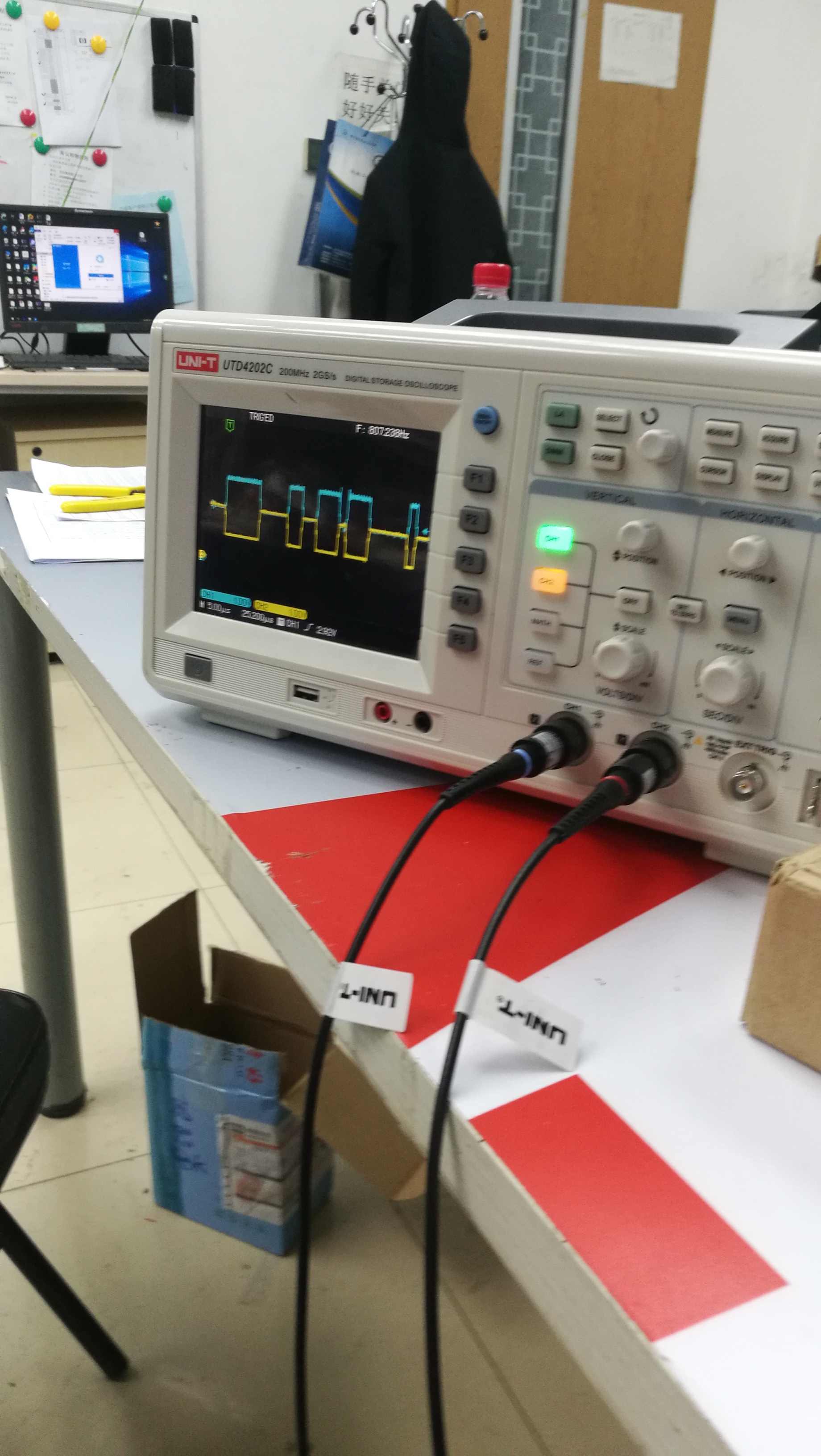
ODrive assumes the CAN PHY is a standard differential twisted pair in a linear bus configuration with 120 ohm termination resistance at each end. ODrive uses 3.3v as the high output, but conforms to the CAN PHY requirement of achieving a differential voltage > 1.5V to represent a “0”. As such, it is compatible with standard 5V bus architectures.
ODrive currently supports the following CAN baud rates:
- 125 kbps
- 250 kbps (default)
- 500 kbps
- 1000 kbps
Transport Protocol
We’ve implemented a very basic CAN protocol that we call “CAN Simple” to get users going with ODrive. This protocol is sufficiently abstracted that it is straightforward to add other protocols such as CANOpen, J1939, or Fibre over ISO-TP in the future. Unfortunately, implementing those protocols is a lot of work, and we wanted to give users a way to control ODrive’s basic functions via CAN sooner rather than later.
CAN Frame
At its most basic, the CAN Simple frame looks like this:
- Upper 6 bits - Node ID - max 0x3F
- Lower 5 bits - Command ID - max 0x1F
To understand how the Node ID and Command ID interact, let’s look at an example
odrv0.axis0.can_node_id = 0x010 - Reserves messages 0x200 through 0x21F
odrv0.axis1.can_node_id = 0x018 - Reserves messages 0x300 through 0x31F
It may not be obvious, but this allows for some compatibility with CANOpen. Although the address space 0x200 and 0x300 correspond to receive PDO base addresses, we can guarantee they will not conflict if all CANopen node IDs are >= 32. E.g.:
CANopen nodeID = 35 = 0x23
Receive PDO 0x200 + nodeID = 0x223, which does not conflict with the range [0x200 : 0x21F]
Be careful that you don’t assign too many nodeIDs per PDO group. Four CAN Simple nodes (32*4) is all of the available address space of a single PDO. If the bus is strictly ODrive CAN Simple nodes, a simple sequential Node ID assignment will work fine.
Messages
| CMD ID | Name | Sender | Signals | Start byte |
|---|---|---|---|---|
| 0x000 | CANOpen NMT Message** | Master | - | - |
| 0x700 | CANOpen Heartbeat Message** | Slave | - | - |
| 0x001 | ODrive Heartbeat Message | Axis | Axis Error Axis Current State |
0 4 |
| 0x002 | ODrive Estop Message | Master | - | - |
| 0x003 | Get Motor Error* | Axis | Motor Error | 0 |
| 0x004 | Get Encoder Error* | Axis | Encoder Error | 0 |
| 0x005 | Get Sensorless Error* | Axis | Sensorless Error | 0 |
| 0x006 | Set Axis Node ID | Master | Axis CAN Node ID | 0 |
| 0x007 | Set Axis Requested State | Master | Axis Requested State | 0 |
| 0x008 | Set Axis Startup Config | Master | - Not yet implemented - | - |
| 0x009 | Get Encoder Estimates* | Master | Encoder Pos Estimate Encoder Vel Estimate |
0 4 |
| 0x00A | Get Encoder Count* | Master | Encoder Shadow Count Encoder Count in CPR |
0 4 |
| 0x00B | Move To Pos | Master | Goal Position | 0 |
| 0x00C | Set Pos Setpoint | Master | Pos Setpoint Vel FF Current FF |
0 4 6 |
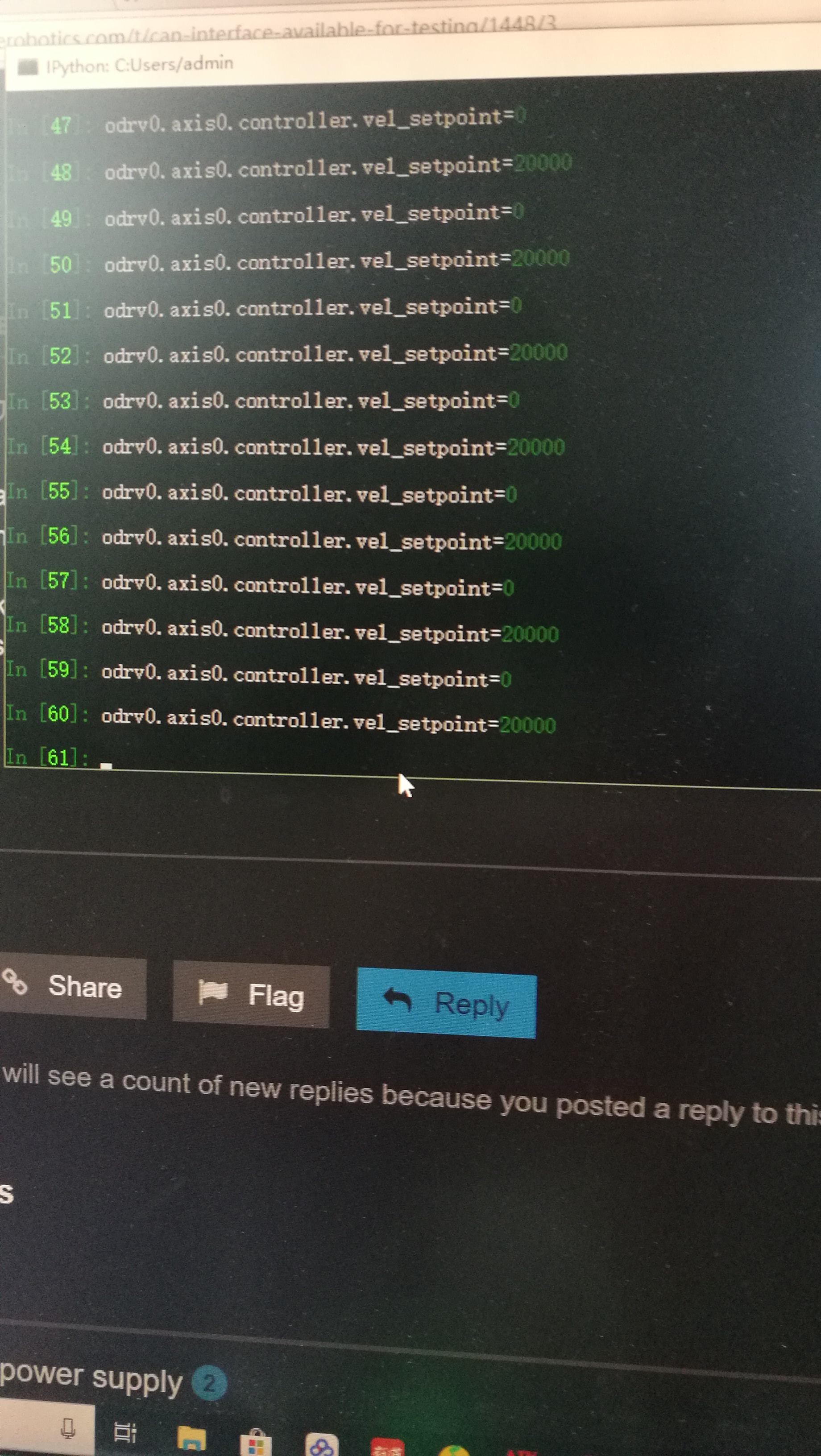
| 0x00D | Set Vel Setpoint | Master | Vel Setpoint Current FF |
0 4 |
| 0x00E | Set Current Setpoint | Master | Current Setpoint | 0 |
| 0x00F | Set Velocity Limit | Master | Velocity Limit | 0 |
| 0x010 | Start Anticogging | Master | - | - |
| 0x011 | Set Traj Vel Limit | Master | Traj Vel Limit | 0 |
| 0x012 | Set Traj Accel Limits | Master | Traj Accel Limit Traj Decel Limit |
0 4 |
| 0x013 | Set Traj A per Count / s^2 | Master | Traj A per CSS | 0 |
| 0x014 | Get IQ* | Axis | Iq Setpoint Iq Measured |
0 4 |
| 0x015 | Get Sensorless Estimates* | Master | Sensorless Pos Estimate Sensorless Vel Estimate |
0 4 |
| 0x016 | Reboot ODrive | Master*** | ||
| 0x017 | Get Vbus Voltage | Master*** | Vbus Voltage | 0 |
* Note: These messages are call & response. The Master node sends a message with the RTR bit set, and the axis responds with the same ID and specified payload.
** Note: These CANOpen messages are reserved to avoid bus collisions with CANOpen devices. They are not used by CAN Simple.
*** Note: These messages can be sent to either address on a given ODrive board.
Signals
| Name | Type | Bits | Factor | Offset | Byte Order |
|---|---|---|---|---|---|
| Axis Error | Unsigned Int | 32 | 1 | 0 | Intel |
| Axis Current State | Unsigned Int | 32 | 1 | 0 | Intel |
| Motor Error | Unsigned Int | 32 | 1 | 0 | Intel |
| Encoder Error | Unsigned Int | 32 | 1 | 0 | Intel |
| Sensorless Error | Unsigned Int | 32 | 1 | 0 | Intel |
| Axis CAN Node ID | Unsigned Int | 16 | 1 | 0 | Intel |
| Axis Requested State | Unsigned Int | 32 | 1 | 0 | Intel |
| Encoder Pos Estimate | IEEE 754 Float | 32 | 1 | 0 | Intel |
| Encoder Vel Estimate | IEEE 754 Float | 32 | 1 | 0 | Intel |
| Encoder Shadow Count | Signed Int | 32 | 1 | 0 | Intel |
| Encoder Count In CPR | Signed Int | 32 | 1 | 0 | Intel |
| Goal Position | Signed Int | 32 | 1 | 0 | Intel |
| Pos Setpoint | Signed Int | 32 | 1 | 0 | Intel |
| Vel FF | Signed Int | 16 | 0.1 | 0 | Intel |
| Current FF | Signed Int | 16 | 0.01 | 0 | Intel |
| Vel Setpoint | Signed Int | 32 | 0.01 | 0 | Intel |
| Current Setpoint | Signed Int | 32 | 0.01 | 0 | Intel |
| Velocity Limit | IEEE 754 Float | 32 | 1 | 0 | Intel |
| Traj Vel Limit | IEEE 754 Float | 32 | 1 | 0 | Intel |
| Traj Accel Limit | IEEE 754 Float | 32 | 1 | 0 | Intel |
| Traj Decel Limit | IEEE 754 Float | 32 | 1 | 0 | Intel |
| Traj A per CSS | IEEE 754 Float | 32 | 1 | 0 | Intel |
| Iq Setpoint | IEEE 754 Float | 32 | 1 | 0 | Intel |
| Iq Measured | IEEE 754 Float | 32 | 1 | 0 | Intel |
| Sensorless Pos Estimate | IEEE 754 Float | 32 | 1 | 0 | Intel |
| Sensorless Vel Estimate | IEEE 754 Float | 32 | 1 | 0 | Intel |
| Vbus Voltage | IEEE 754 Float | 32 | 1 | 0 | Intel |
Configuring ODrive for CAN
Configuration of the CAN parameters should be done via USB before putting the device on the bus.
To set the desired baud rate, use <odrv>.can.set_baud_rate(<value>). The baud rate can be done without rebooting the device. If you’d like to keep the baud rate, simply call <odrv>.save_configuration() before rebooting.
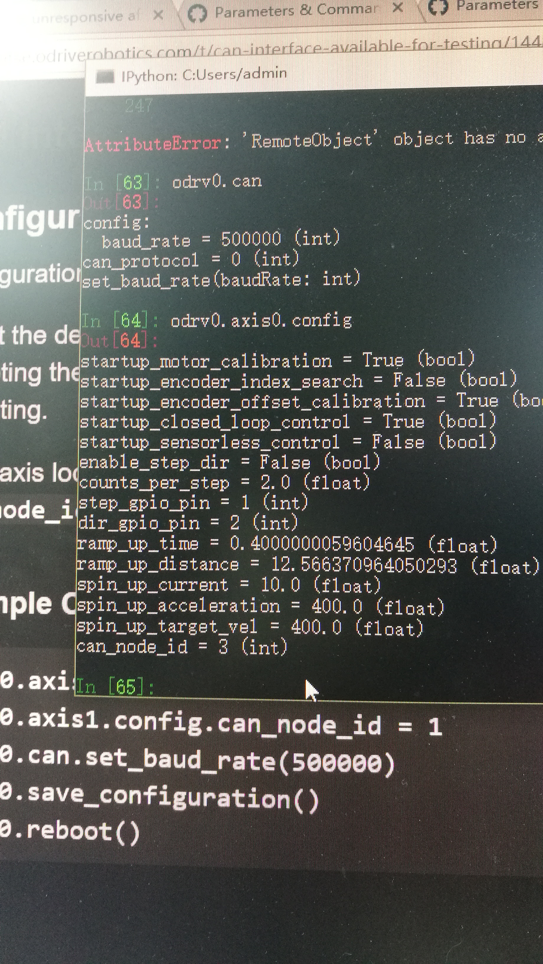
Each axis looks like a separate node on the bus. Thus, they’ve inherited a new configuration property: can_node_id. This ID can be from 0 to 63 (0x3F) inclusive.
Example Configuration
odrv0.axis0.config.can_node_id = 3
odrv0.axis1.config.can_node_id = 1
odrv0.can.set_baud_rate(500000)
odrv0.save_configuration()
odrv0.reboot()