Hello! Wanted to run a quick confirmation on my wiring diagrams for two set-ups to confirm that my wiring is correct and I don’t have ground loops. Let me know if I need to correct anything!
Also, I don’t understand the CAN termination process and what I need to do for this.
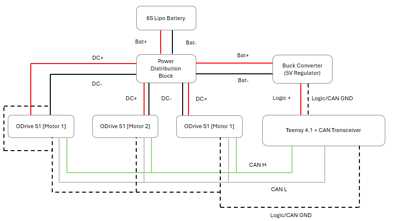
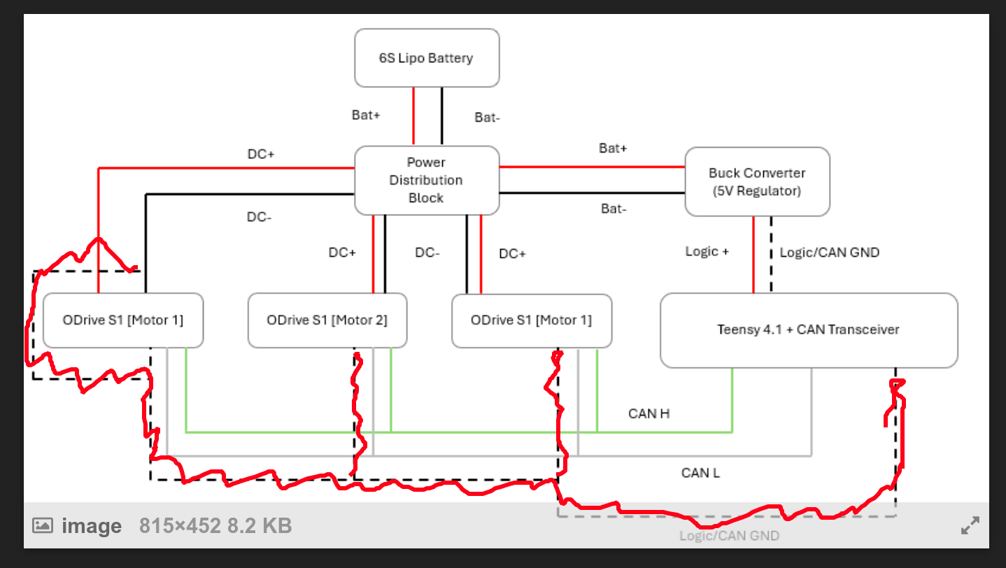
Hi! In the first case, you don’t strictly need the CAN tie from the Teensy, as the S1 already uses the DC- for the CAN ground reference, and your buck converter’s output will be referenced to the BAT- (aka DC-). So you should just delete this whole wire (highlighted in red):
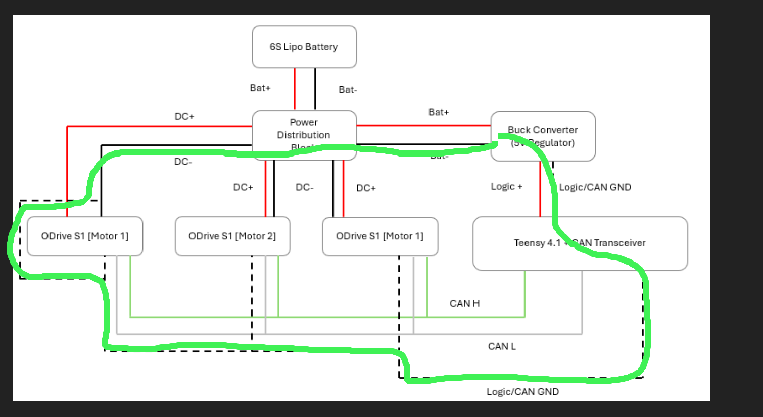
Otherwise you run the risk of a ground loop, highlighted in green:
I don’t think you’d actually break anything in this situation, but it’s good practice to be careful.
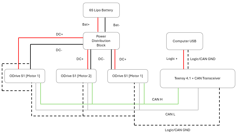
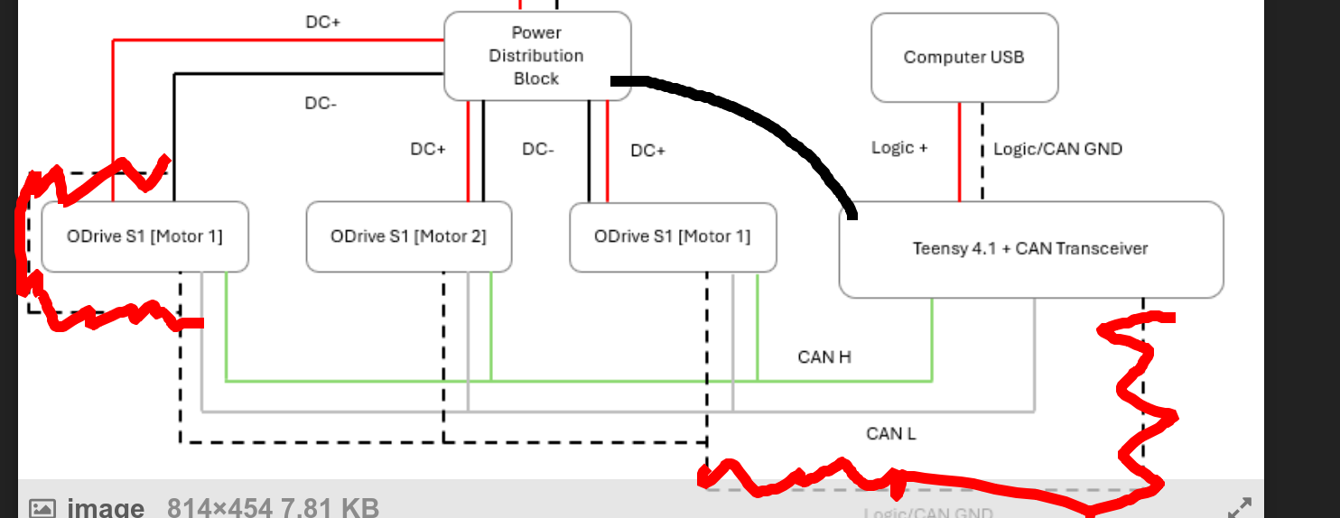
In the second situation though, this looks great! Since the computer has no ground connection to the battery/PDB ground, the Teensy needs the explicit ground tie you have there.
Note that overall, the CAN GND daisy chaining through the S1s isn’t strictly necessary, it’s just a way of making wiring a bit easier if you’re already using our JST-GH CAN cables. Another way of doing this would be to remove the connections highlighted in red and make a ground link to the power distribution block (black):
Regarding CAN termination – CAN requires each “side” of the bus to have a 120ohm resistor bridging CANH and CANL. So in this case, your Teensy’s CAN transciever likely has this onboard, and then you’d also want to flip the DIP switch labeled “CAN” (next to the USB port) on the S1 w/ Motor 1 from “NO R” to “120R”