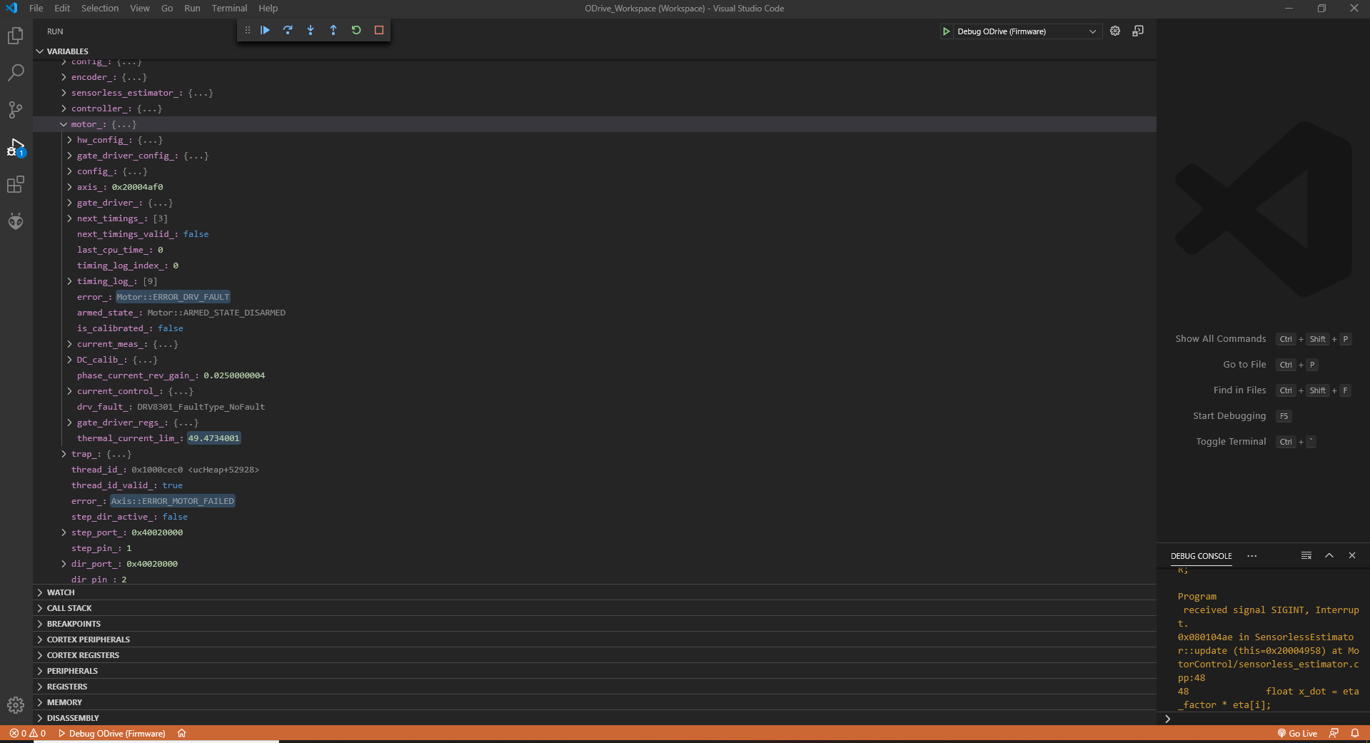
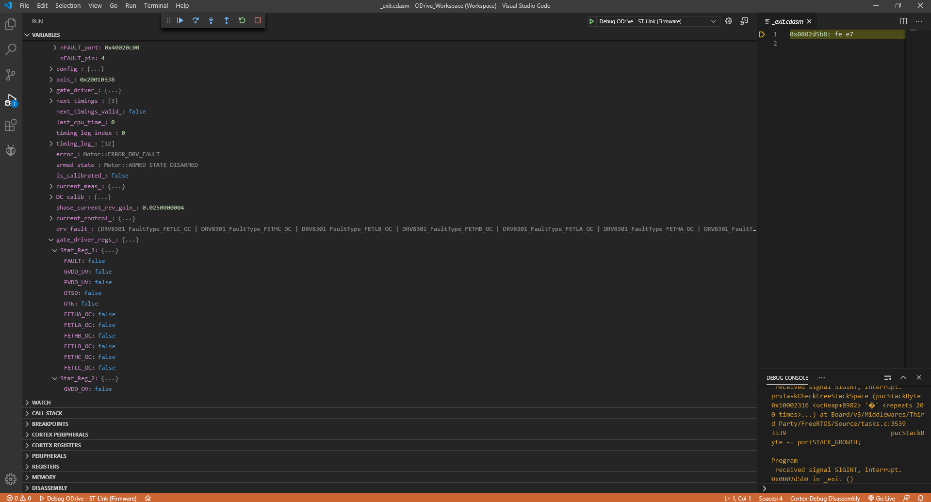
I have found out the issue with the DVR faults and it’s a few capacitors which are quite critical I have now found out about after coming across this document. https://www.ti.com/lit/an/slva552/slva552.pdf?ts=1591088046139 Moved 2x capacitors with jumpers and no more DRV Errors.
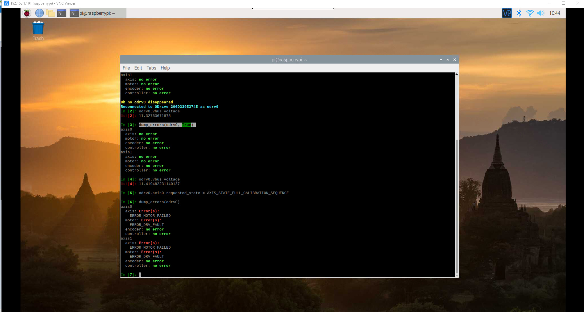
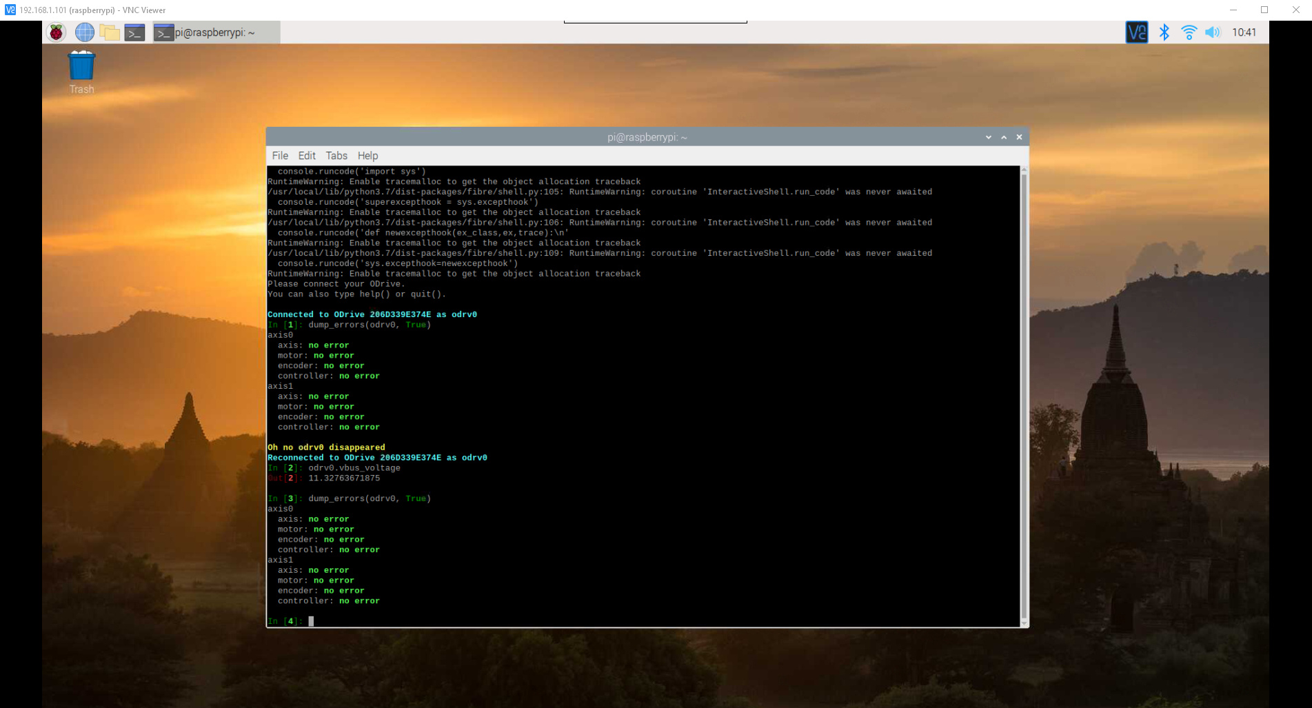
I can now calibrate the motor fine with no error and everything reports back good and comes back true calibration etc encoder is working well and everything comes back ready to go. If i put it into velocity mode and set a velocity setpoint nothing happens and I get no errors. I get similar with position mode. When I put it into closed loop it will hold position slightly but if I turn it to much it will just stay there and not drive back. If I give it a position setpoint it will not do anything and does not report back any errors. I have tried both the Master and Devel branch and same results.
Does anyone know what could be causing this and what else to try from here?
UPDATE:
The issue I was having seemed to be an issue with the voltage divider and vbus reading wrong. I am using 10k and 510R ( tried with 470R but worse ) I could not find the exact values required on the schematics as they only show 24v version. I found the vbus reading was 1v upto 4v out as I increased the voltage. I have now changed the voltage divider ratio from 19 to 21 and now reading almost spot on ( around 100mv difference from multimeter ) I’m not sure how accurate this has to be. I ran through the calibration process and adjust PIDs and now I can use Position and Velocity Control. Now I’m running into cogging issues at low speeds. The BLDC motor is 4 pole pair so whether this is just the nature of having low pole pair motor. I will now start looking into anti cogging and report back with my findings
UPDATE:
Mucked around with anti-cogging but caused motor to get really hot and was taking over 10 minutes so had to cancel every time. I had issues once I ran the process I could no longer use velocity control etc I then reflashed stm and still same issue, in order to get rid of this problem I had to do full chip erase in ST-Link and then reflash firmware. I then had todo every calibration process again as even loading a saved configuration that had been running previously would not work. So some strange stuff going on there.
I decided I would just continue to muck around with the PIDs some more in Velocity mode since this is what I will end up using with 0-100% PWM Input and direction. The motor has no load on it and encoder is 1800ppr. I can get it quite stable with small vibrations at 0 ( can’t get rid of them at any setting ) in order to get running smooth at 1000 c/s my P = 0.00012 and I = 0.015 and If I bring the Velocity above 50000 c/s it becomes quite unstable and at 300000 c/s it cut’s out on unstable current sometimes. If I drop the I = 0.005 it’s very smooth right upto 500000 but barely rotates 1000 c/s it has large cogging. I can’t seem to find a sweet spot for the PIDs over such a large range.
Is there a way to have the PID values change once velocity is over a certain point or something along those lines. maybe there are some other settings i’m missing that could be adjusted?
UPDATE:
I changed the encoder bandwidth from 1000 to 2000 and that made a massive difference, I no longer get any vibrations with 0 velocity and I can run it from 100 c/s all the way up to 500,000 c/s without it going crazy and staying nice and smooth, great results. I can’t find much info on the encoder bandwidth and what it exactly does, but it does make a huge difference, so if anyone could explain that would be awesome.
Now I need to implement 0-100% PWM upto 10khz. I see in the RC PWM the maximum is 500hz because it is using an interrupt. I’m guessing I would need to access hardware timers/counters in order to implement this. I’m new to embedded programming and only done few small arduino stuff, so if someone could lead me in the right direction or maybe I’m best creating new post for this feature, I have seen it come up a few times, but nothing implemented yet. The reason for 10khz is the frequency the Kflop CNC controller outputs and they recommend not going below this.