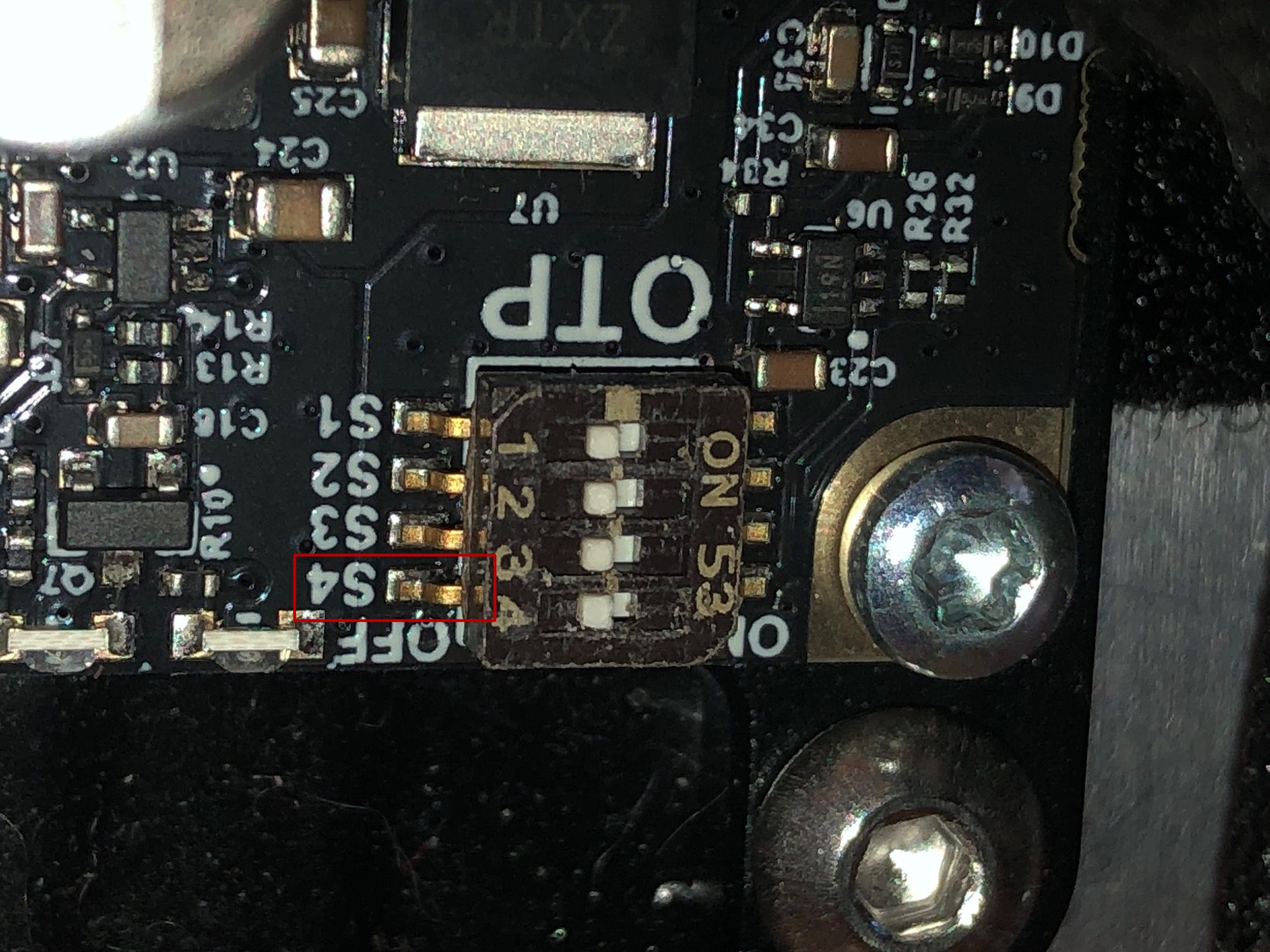
Hey guys, was wondering if I could get some help figuring out how to get the regen clamp working. I am trying to disable the OTP threshold (Red LED) because I do not have a thermistor connected to the regen clamp. Based on the datasheet, I understand I need to set the top-most switch on the DIP array (OTP EN) to OFF. However when I look at my regen clamp, I do not see OTP EN, only “S1, S2, S3 S4”.
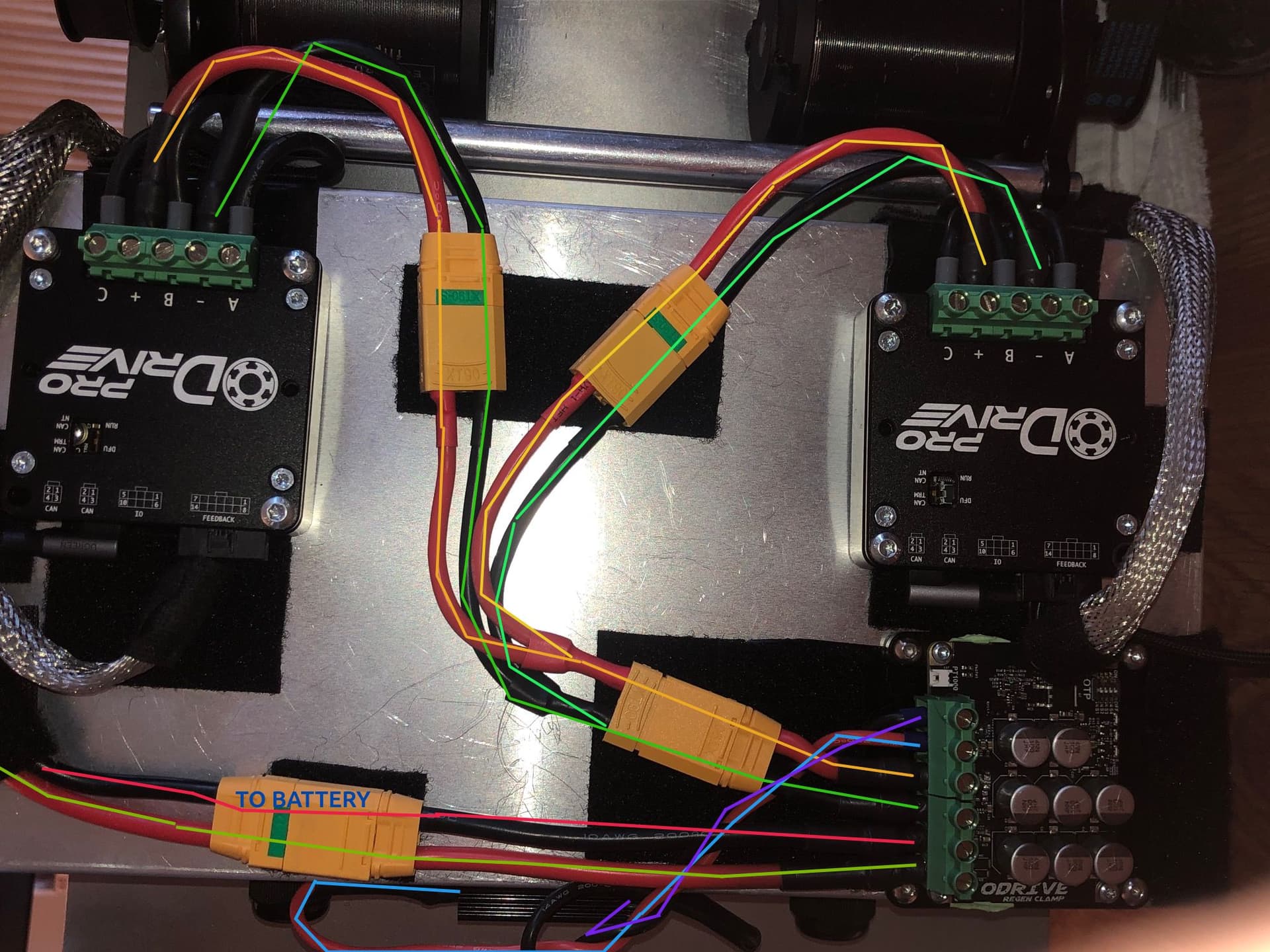
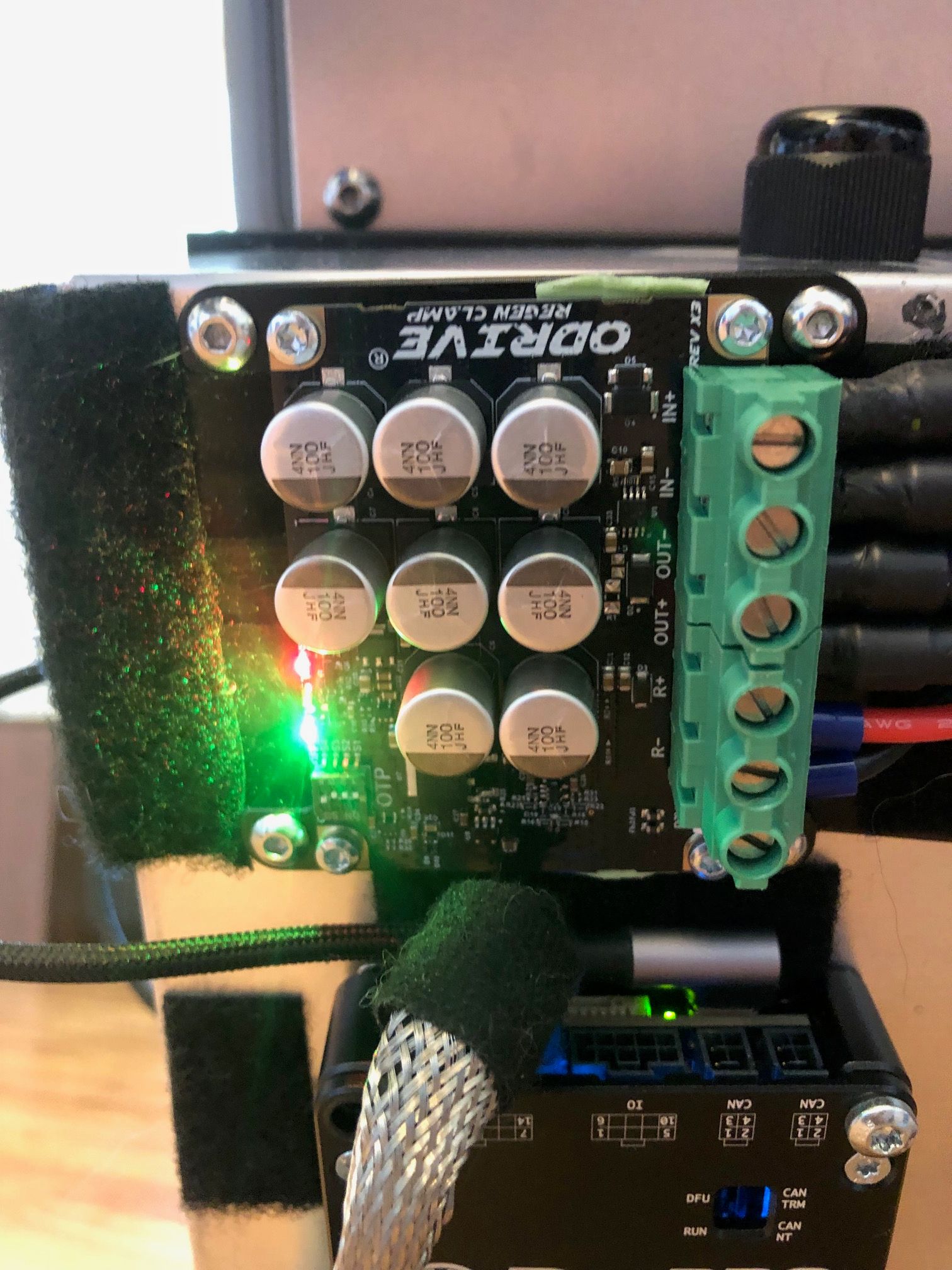
Furthermore, when I switched all the switches off, the red LED still remained on. Various combinations (all switches set to on, any single switch set to off with all others set to on, etc.) all produced the same result. I’m not sure what I am doing wrong, but I could use some guidance. Let me know if you guys have any suggestions! I’ve attached some pictures of my wiring and closeups of the regen clamp.
1 Like
Hi!
On the regen clamp, board the OTP enable is S4, the one you boxed. S1-S3 set the threshold as in the datasheet table, which still shows the older board’s labels (we’ll fix that).
The clamp won’t brake at all while the red LED is on. With S4 OFF it should go out right away (no power cycle needed), so if it stayed on with all four switches pushed fully to OFF, I think something’s wrong with the board. Shoot us an email at info@odriverobotics.com referencing this thread.
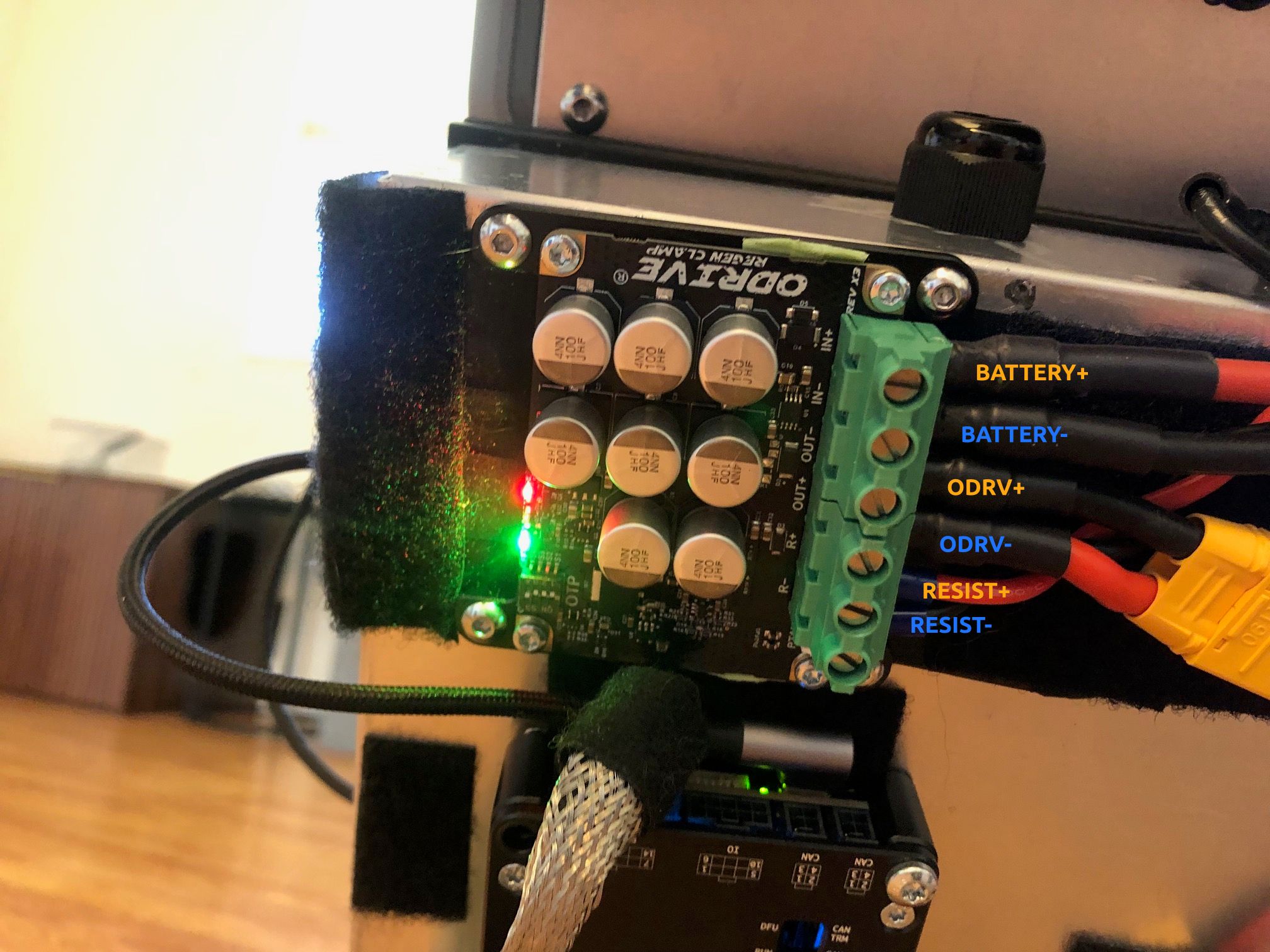
Also, your labels in the second photo put ODRV+ on the terminal marked OUT- (the order is IN+, IN-, OUT-, OUT+, R+, R-). Probably just the labels, but worth a quick check with a meter.
1 Like
Ah makes sense, thanks for the info Solomon! That probably also explains some of the dc_bus_overvoltage error messages I was getting during trial runs. And yep, my ODRV+ and ODRV- labels were reversed in second photo, thanks for the heads up. I’ll send out the email shortly.