For the above tests I was using a recent devel from maybe 3 weeks ago at the most…
I tried to repeat with the most recent obe, but ran into an issue (see Failed to flash firmware using odrivetool from latest devel)
Just the encoder. A previous Odrive died while that same encoder was plugged in, so my working theory is that it took it with it.
That could potentially mean everything I’ve done since the start of this thread was with a damaged bit of kit.
Anyway, I’m now waiting on a new one to be delivered and am out for the count until then.
Ok, now that DFU is working, I have updated my firmware to the latest devel
Unfortunately, I get the same issue.
After a few seconds (without any PWM enabled) I immediately get ENCODER_ERROR_ABS_SPI_COM_FAIL - nd on the scope I can see that the encoder has set its error bit, but is otherwise returning an apparently valid position.
In [7]: odrv0.axis0.encoder.spi_error_rate
Out[7]: 0.5088629722595215
Liveplotter as before, while turning the motor by hand:
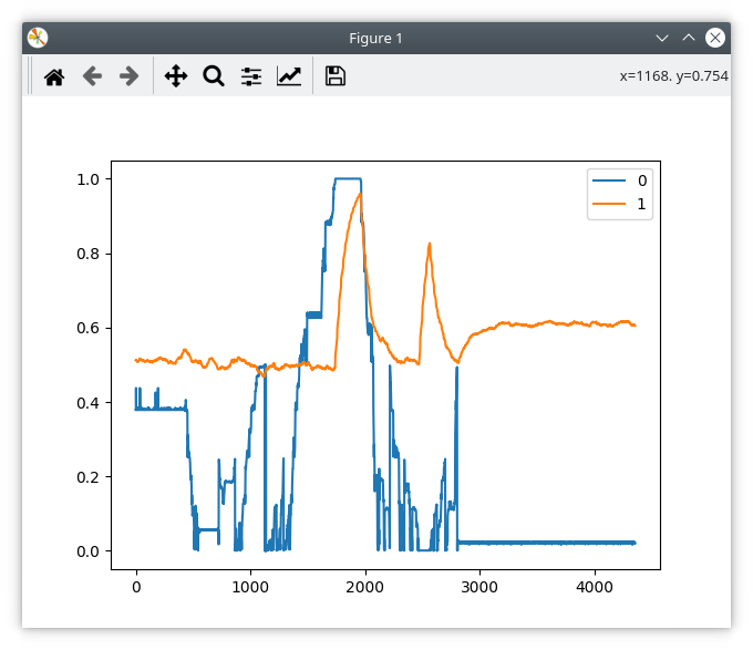
Looking at this, It’s almost as if the ODrive is reading the MSB of the data and interpreting it as the error flag?
But then if that were the case, then I wouldn’t get spi_error_rate=0.5 in any position except right on the MSB boundary.
So it’s more like it’s interpreting (MSB + LSB) as the error flag… ??? 
Tom, are you able to build the firmware from source?
If so, can you check if this fixes the problem? It’s in encoder.cpp, line 566. If not, I can build a version and send it to you.
1 Like
Hi Wetmelon,
Unfortunately, no. It seems to make no difference. 
Liveplotter trace: (turning motor steadily by hand anticlockwise)
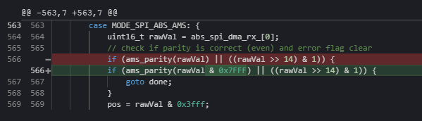
This is my full diff from latest devel:
diff --git a/Firmware/MotorControl/encoder.cpp b/Firmware/MotorControl/encoder.cpp
index 2dcb70ba..95dd122b 100644
--- a/Firmware/MotorControl/encoder.cpp
+++ b/Firmware/MotorControl/encoder.cpp
@@ -563,7 +563,7 @@ void Encoder::abs_spi_cb(bool success) {
         case MODE_SPI_ABS_AMS: {
             uint16_t rawVal = abs_spi_dma_rx_[0];
             // check if parity is correct (even) and error flag clear
-            if (ams_parity(rawVal) || ((rawVal >> 14) & 1)) {
+            if (ams_parity(rawVal & 0x7FFF) || ((rawVal >> 14) & 1)) {
                 goto done;
             }
             pos = rawVal & 0x3fff;
diff --git a/tools/odrive/utils.py b/tools/odrive/utils.py
index 73489130..75e52783 100755
--- a/tools/odrive/utils.py
+++ b/tools/odrive/utils.py
@@ -133,7 +133,7 @@ def oscilloscope_dump(odrv, num_vals, filename='oscilloscope.csv'):

 data_rate = 200
 plot_rate = 10
-num_samples = 500
+num_samples = 5000
 def start_liveplotter(get_var_callback):
     """
     Starts a liveplotter.
diff --git a/tools/odrivetool b/tools/odrivetool
index 5d0e9776..4ad9e67a 100755
--- a/tools/odrivetool
+++ b/tools/odrivetool
@@ -157,8 +157,8 @@ try:
         # If you want to plot different values, change them here.
         # You can plot any number of values concurrently.
         cancellation_token = start_liveplotter(lambda: [
-            my_odrive.axis0.encoder.pos_estimate,
-            my_odrive.axis1.encoder.pos_estimate,
+            my_odrive.axis0.encoder.count_in_cpr/16384.0,
+            my_odrive.axis0.encoder.spi_error_rate,
         ])

         print("Showing plot. Press Ctrl+C to exit.")
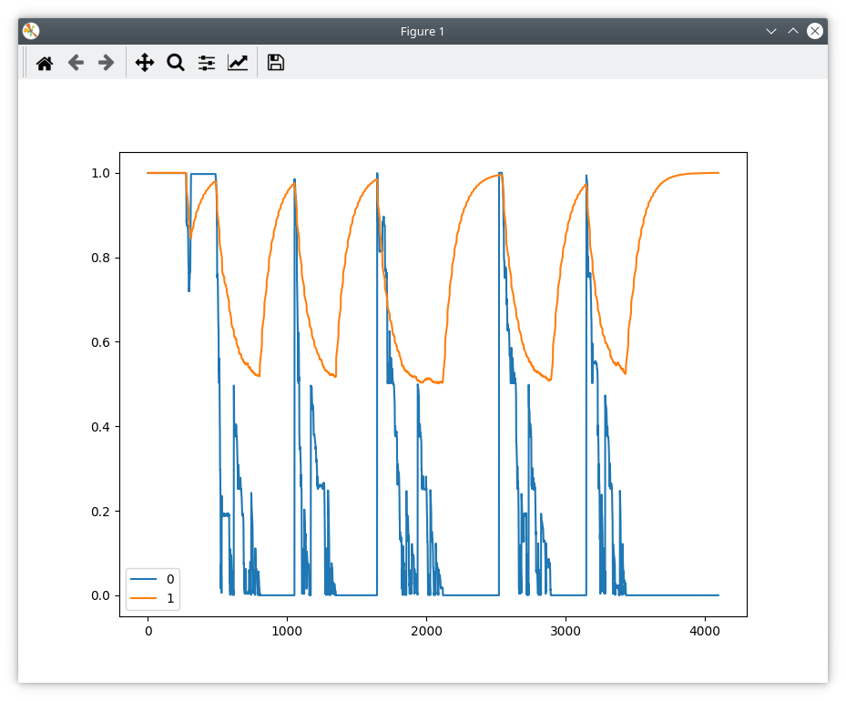
For the sake of sanity, I tried commenting out the whole IF statement with the goto, and I got this:

It is as if there really is some flag that is set 50% of the time, and is corrupting the data.
I do have an ST-Link, would it be worth setting up a debugger? Or perhaps I will check my scope traces against the chip’s datasheet to see wtf it is really sending.
Also, I tried a second time (no changes except system power cycle including encoder) and I get this: (motor turning steadily clockwise by hand)
Since i’m getting variable results, I will remove my hack and try your code again, but I don’t think it’s going to work since clearly the position data is wrong.
OK, some progress, I think??
I went back to my scope, and I noticed that I was getting those bogus SPI transitions. The scope was ficking between two traces:
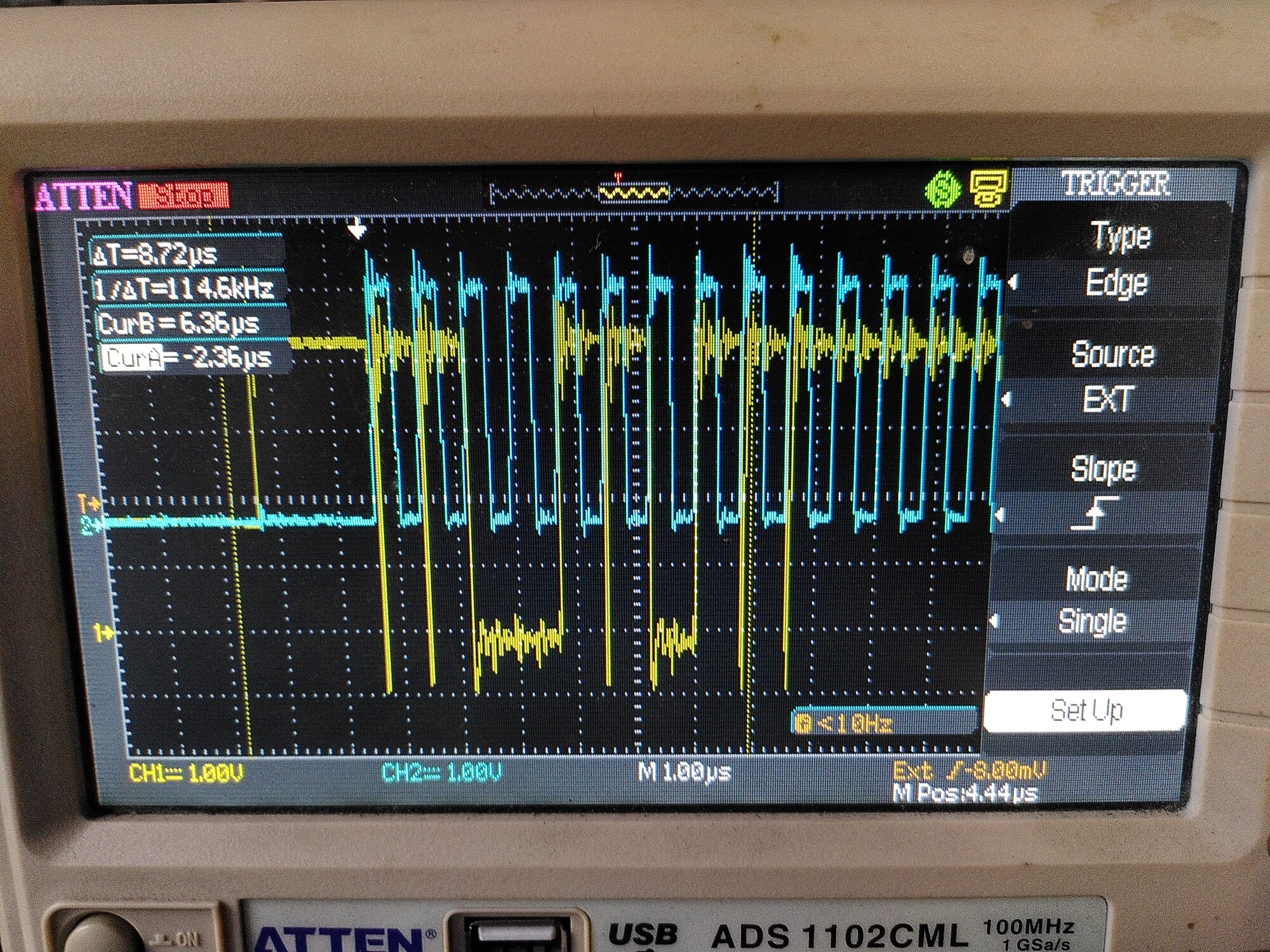
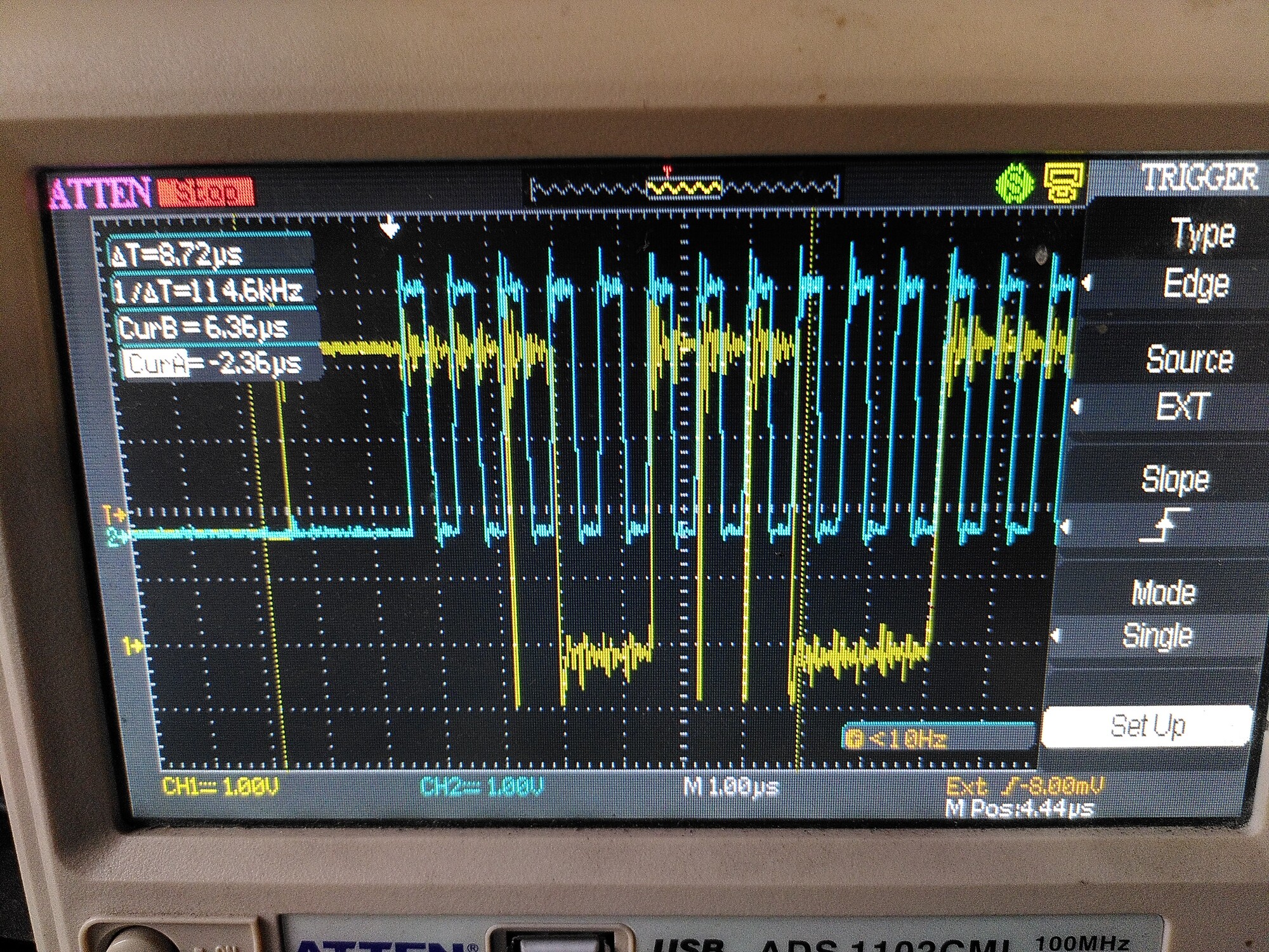
I remembered about the 50R resistor. I didn’t have 50R to hand but I used 100R, and put it in what I thought was the SCK wire. Actually it was MISO.
That made a big difference. The position looks good now, although SPI_error_rate is still hanging around 0.5, in all positions.
Then I thought OK, i’ll do the other wires, which is when I noticed my error.
So I put a resistor in line with SCK, and left the one I put in MISO.
That made things worse. 
To illustrate, the plot below is with 100R in line with MISO on the left (the resistor on SCK is shorted out). The right part is where I remove the short, and put 100R in line with SCK.
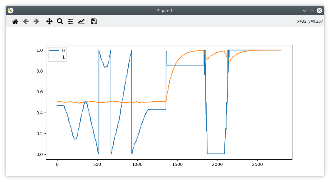
Interestingly, I can see the difference on the scope.
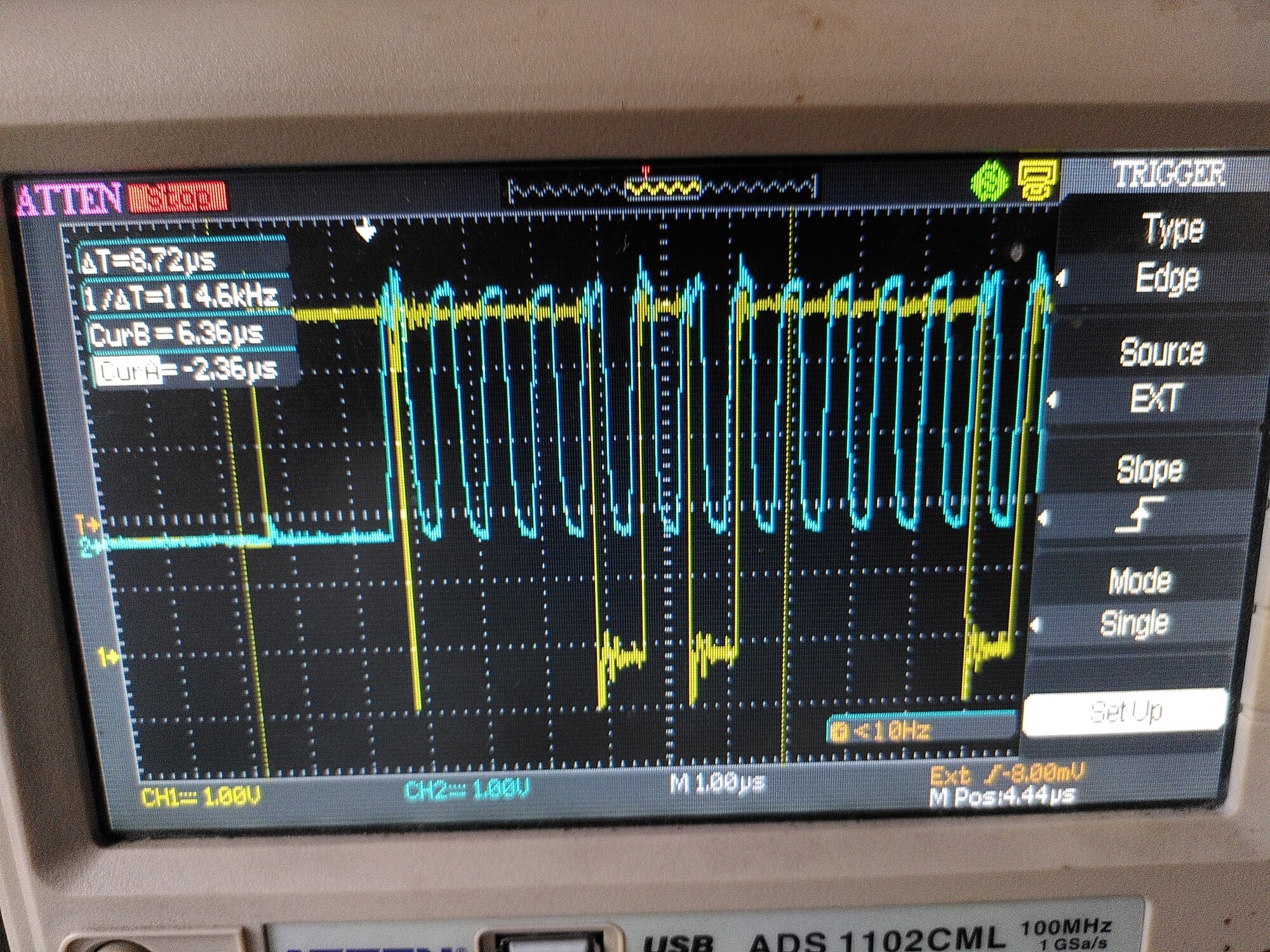
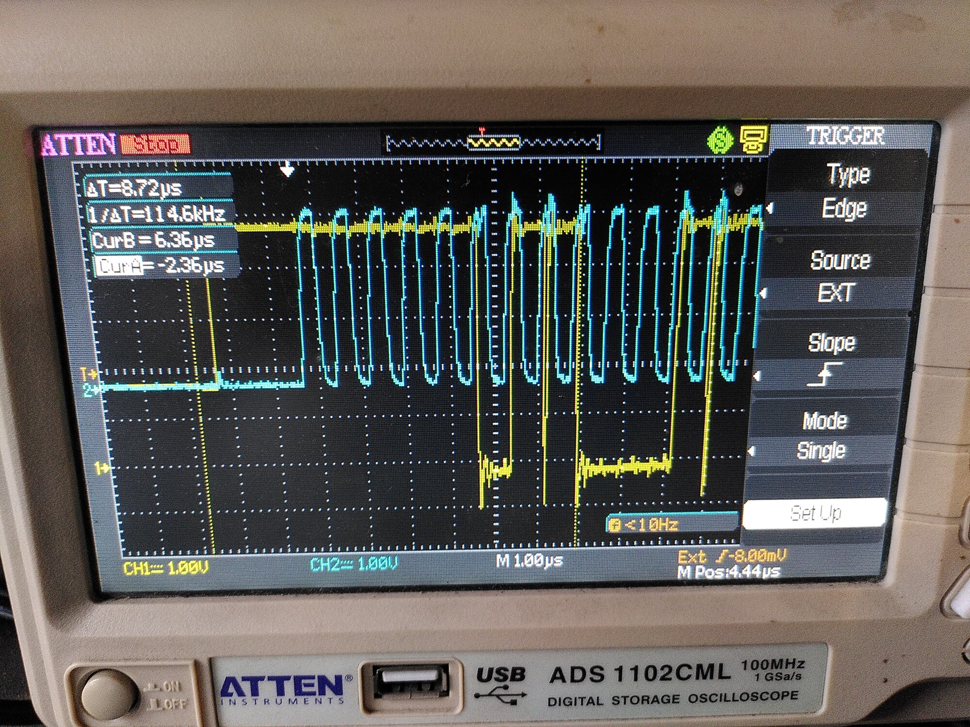
The first trace is with 100R in line with MISO (in yellow, but the probe is on the encoder side of the resistor) and no resistor on the clock (because it’s shorted out).
The other two are with the short removed, so 100R on the clock too.
You can see those weird transients appearing on the second and third trace.
Ill see if I can get hold of some of the recommended 50R and get back to you. 
And no, I don’t think it was anything you did in the code that caused this - i’m pretty sure it still happens on your old RazorsEdge branch which is what I was using in 2019. It’s probably definitely maybe a SPI issue. But Why the pitch-forking hell is it happening now, when I had no issues whatsoever in 2019-2020 until they all slowly started to degrade to this state with no changes to hardware or software.
It’s as if these chips have all caught covid and died. 
EDIT: Ok last post for a bit. I found some 20R resistors. I put one in the SCK wire.
Again, it is worse than having no resistor…
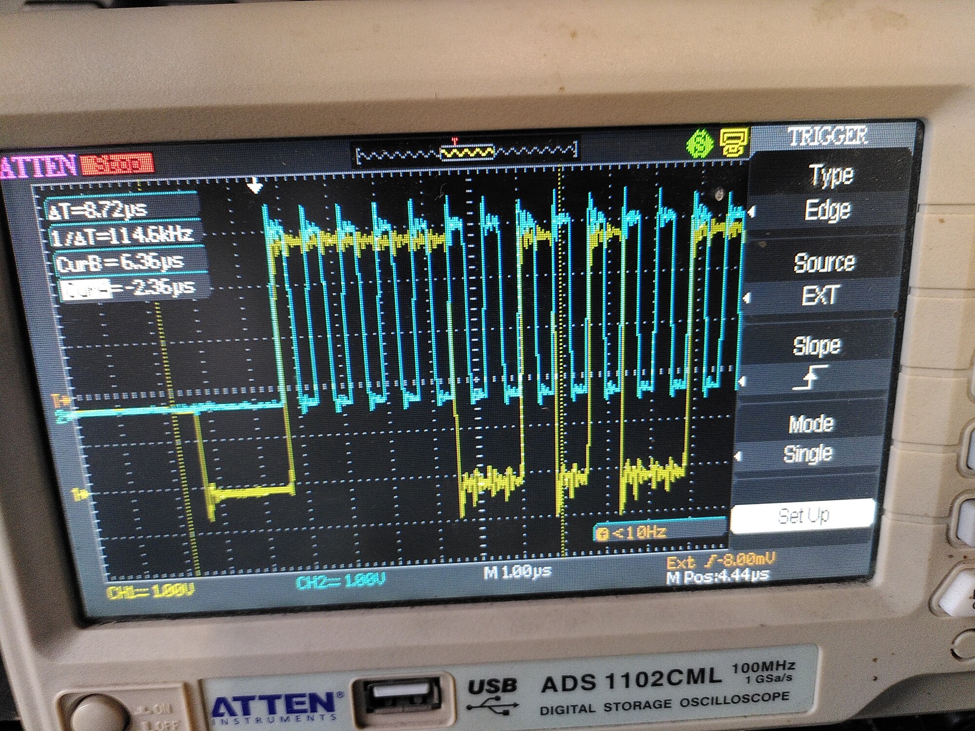
Graph to illustrate: I short out the resistor, move the motor by hand a few turns, then remove the short and repeat the same movement:
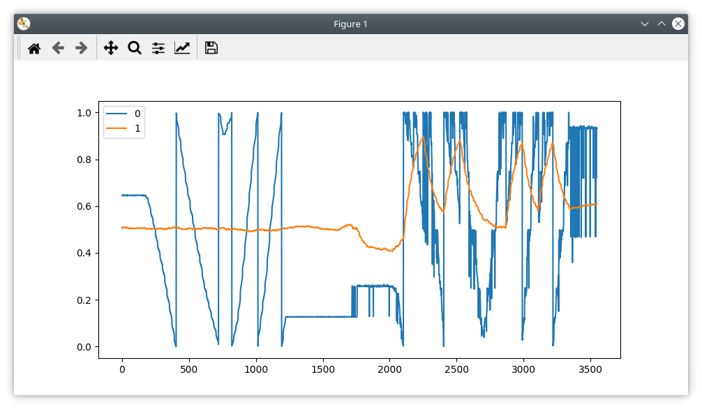
On the scope, I can see that the clock looks much cleaner, but there are those weird transients now present on MISO, like this:
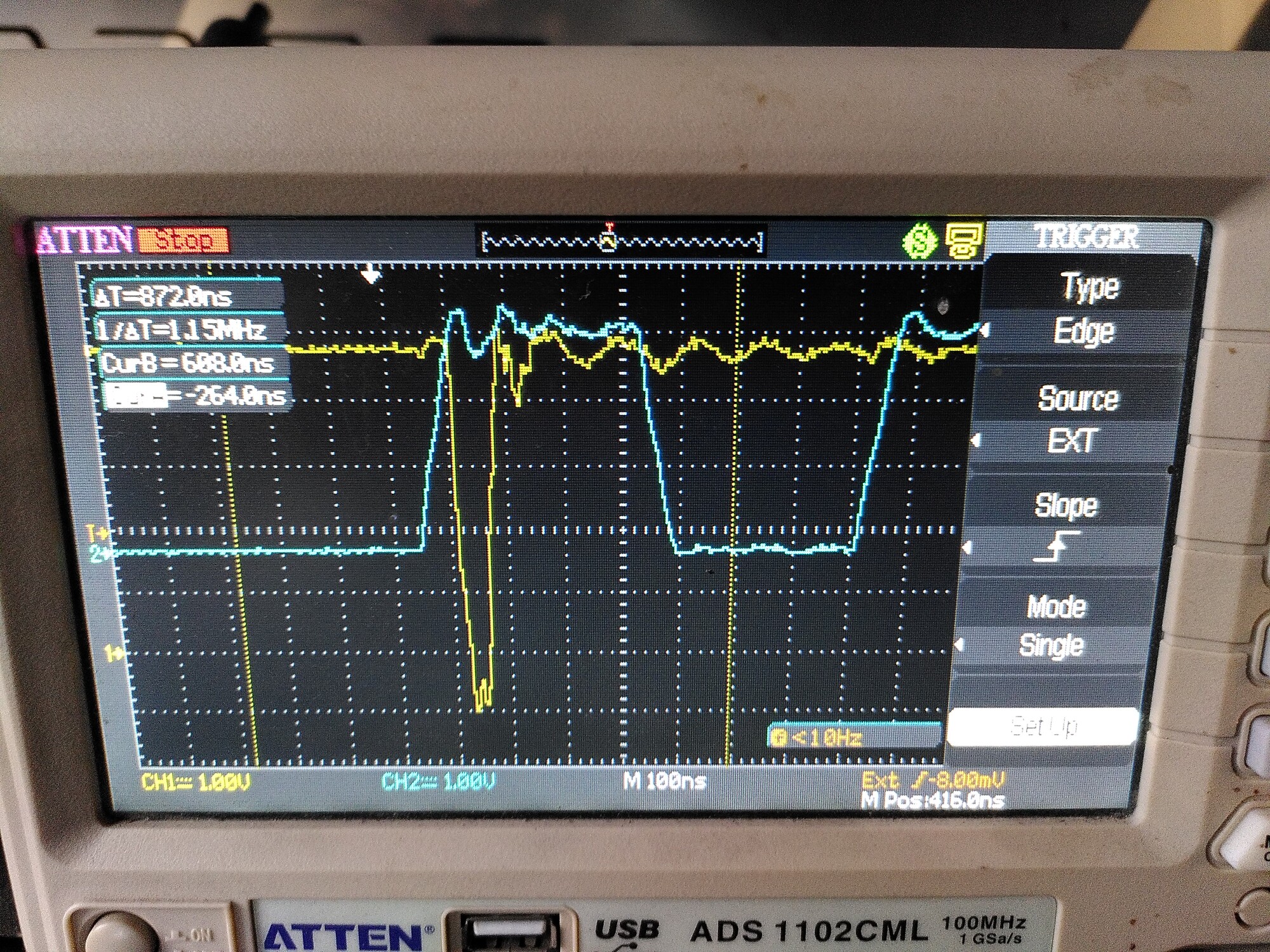
(Blue is the clock. MISO should never change state at a higher rate than the clock)
It must be seeing some noise and interpreting it as a clock edge. But the probe is on the encoder side - there is hardly anything there to cause that.
Yeah, ignore the software thing, turned out to be fine how it was. I assume the encoder is in 3.3v mode?
Hmm no, I haven’t moved any resistors, and it is supplied with 5V. So it is in 5V mode.
But then again, it always was.
I suppose it’s possible that it was just on the edge of working before.
It should be TTL levels in 5v mode but who knows. Maybe try running it in 3.3v mode?
I’d rather not… It’s quite a faff moving those 0203? resistors and I’ve already destroyed one board trying. I’m sure it is supposed to work in 5V mode.
Do you know what the reasoning behind having the inline resistors in SPI is?
Yeah, they slow down the slew rate of the SPI lines, it’s supposed to help with ringing
Hi,
I have had similar problems with the AMS encoder for a while now and fixed it now by ignoring the errorflag that is received. I added a:
bool ignore_abs_ams_error_flag = false;
to Encoder ::Config so the error is not ignored by default. Would you like me to make a PR for this? It seems a lot of people have trouble with this encoder and this might help at least some of them. If yes, which branch should I merge into?
regards
grahameth
@grahameth - I did something similar, but just ignored the error flag and didn’t make this configurable. I just wanted to add a “thumbs-up” to having your config flag available in the standard codebase…
Did you by any chance look into what it would take to actually clear the error flag when it happens? I started to look into it - clearing the error flag should just entail reading from register addr 0x0001. However, given the way the chip works for reads (the requested data is available on the following read) I wasn’t comfortable with the amount of changes that would be necessary in the current firmware to follow through on it.
In a ‘perfect’ world I think this would be the best solution - when an error is flagged, don’t use the reported position value (even though it seems to be valid) and issue a cmd to clear the error (read from 0x0001), ignore the subsequent response to this cmd, as it’s not a position report. If all is well the next position report should be ok.
Just thinking out loud…
Hi kizmit99,
thanks for the thumbs up 
Yes, I also initially wanted to fix this “the right way” by sending a command to the chip, but I couldn’t figure out how. The changes to the codebase would probably be quite involved, but I didn’t spend too much time looking into it. Also, since the official guide suggests to connect MOSI directly to VDD, I didn’t want to undo that (it would be quite a hassle in my setup). That said, if the official developers would prefer this, I can look into it again.
best regards
Please send us a pull request targeting the devel branch (or 0.5.2rc1)
Ok, here it is: Add ignore_abs_ams_error_flag by hbuhle2s · Pull Request #563 · odriverobotics/ODrive · GitHub
1 Like
An update to this: Ignoring the errors does indeed help (I haven’t tried Graham’s code, but I put in my own change):
-- if(spi_error_rate > 0.05)
++ if(spi_error_rate > 0.5)
could maybe do with a variable spi_error_tolerance or something.
The other thing that has helped a LOT is to run the AS5047p on 3.3v instead of 5v.
The only reason I can think of for this to make such a difference, is if there is a lot of noise on ODrive’s 5V rail.
So far I have not moved the resistor for 3.3v either - it seems to work fine regardless.
I have come back to this and I’m getting some really weird behaviour.
I have been using incremental mode for a while now with no problems at all (that I can see) so I’m pretty sure it’s specific to this SPI problem.
I am currently unable to run the AXIS_STATE_FULL_CALIBRATION_SEQUENCE all the way through because spi_error_rate jumps too high. So I have followed all the suggestions I could find on this thread and others to try to reduce noise.
To be specific, I have tried
- using 3.3V instead of 5V, making sure to use the same header as the SPI wires use.
- putting resistors in series with the SCK line. (I tried 10R and 100R, only having one of each, and not having anything between 20R-50R.)
- disabling the error bit check in the firmware as @grahameth did.
- increasing the
spi_error_ratethreshold to 0.5 as @towen did. - replacing the five SPI wires with fatter cables, and braiding them together.
- improvising a ferrite ring and wrapping the motor cables around it.
- tying the metal chassis to ground
What I’ve noticed as I was trying these is that for a few moments, each change would appear to be an improvement. Then, all of a sudden, that improvement would be ‘undone’.
This was especially noticeable with the ferrite ring. There, the error rate fell to pretty much zero. It stayed that way for one or two first-halves of a calibration cycle (which wasn’t finishing due to an unrelated config error I found and fixed.)
But then, all of a sudden, it was as if everything suddenly went back to its pre-ferrite-installation behaviour. Ie - the error rate shooting up straight away and the calibration cycle erroring out with ENCODER_ERROR_ABS_SPI_COM_FAIL
I had made no changes at all to cause this. I was simply running odrv0.axis0.requested_state = AXIS_STATE_FULL_CALIBRATION_SEQUENCE followed by dump_errors(odrv0,True) over and again, just as I had been before.
Then I tried it again after a ten minute pause, and found that it “worked badly” for one single run, then resumed not working at all after that. By “working badly”, I mean the spi_error_rate got worse and worse, but at a slower rate than it had been. By not working at all, I mean the spi_error_rate shoots up over the threshold straight away.
Further testing confirms that I can reliably get one single bad half-run, if I wait ten minutes after the last failure, and any subsequent tries (without waiting) end in immediate failure.
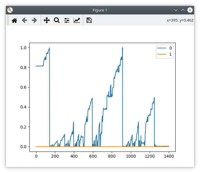
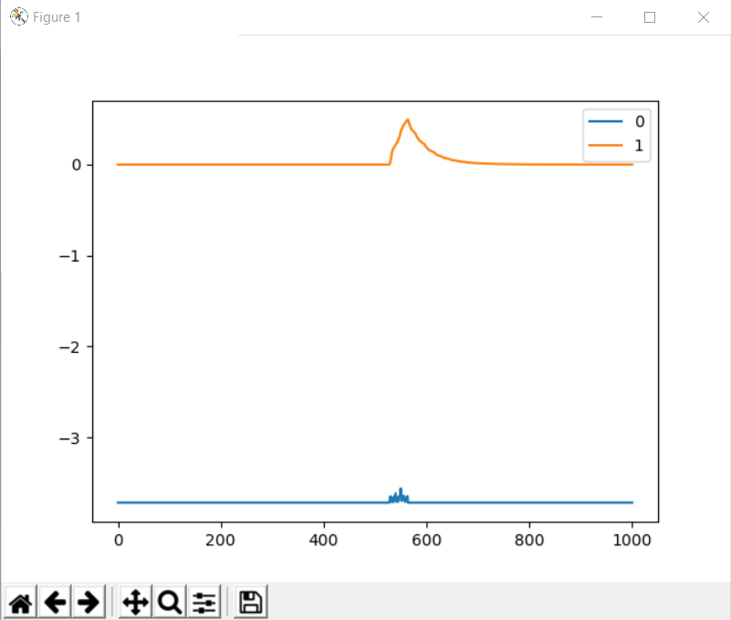
Here is a screenshot of the “bad but trying” calibration run: (Sorry for the poor quality.)

spi_error_rate is orange, pos_estimate is blue. 0.5 is the post-@towen bomb-out threshold for the spi_error_rate, so once the orange line gets higher than that the Odrive errors out. I don’t know why the pos_estimate is glitching out like that, unless comms noise is able to do that.
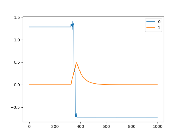
Here is a screenshot of what you get every time, if I run the calibration cycle again without waiting for ten minutes:
Sometimes the pos_estimate glitches - the pedals barely twitch but it reports a large turn:
Does anyone have a clue what might be going on?
Immediately after installing the ferrite ring, that orange line was totally flat, and now suddenly it’s acting like this. I am doubting my sanity here.
Is this the most robust way to improve SPI encoder to work? So far i did a few experiments. but i think i come to the conclusion that it is a “DON’T”.
1 Like

Here’s the video from the OpenDog creator. He uses AS5047 SPI Encoders on his robot with no issues at all. I asked him in the comments how he was able to acheive this, and he said that there’s nothing special, he just followed the ODrive documentation and it just works. What are we doing wrong?
1 Like