I am having serious problems getting an AS5047P to work with an SPI, and am at my wits end with it. I have been using incremental mode for a while now with no problems at all so I’m sure it’s specific to SPI and the SPI noise issues that have been talked about before on this forum.
What I am seeing is that, whenever I try a physical fix to reduce noise levels, the spi_error_rate value improves for a short time, then mysteriously “undoes” itself and goes back to how it behaved before.
But the physical fixes are still there. I haven’t taken them out. It’s as if the background noise level is taking them into account and increasing itself to compensate, in some sort of cosmic closed loop control.
I got the impression this was happening as I was going along, and dismissed it because it felt insane. But on trying the ferrite ring, the spi_error_rate dropped completely to zero, and I cheered success.
Which made it undeniable when, a moment later, the error rate changed its mind and went back to doing what it was doing before.
Does anyone at all have any ideas here?
Detail:
- I am trying, but currently unable, to run the
AXIS_STATE_FULL_CALIBRATION_SEQUENCE. - Currently you can’t complete the cycle all the way through because
spi_error_ratejumps too high. - So I have followed all the suggestions I could find on this board to try to reduce noise.
To be specific, I have tried
- using 3.3V instead of 5V, making sure to use the same header as the SPI wires use.
- putting resistors in series with the SCK line. (I tried 10R and 100R, only having one of each, and not having anything between 20R-50R.) (I have now taken these out again because they made no difference.)
- disabling the error bit check in the firmware as suggested here.
- increasing the
spi_error_ratethreshold to 0.5 as @towen did here. - replacing the five SPI wires with fatter cables, and braiding them together.
- improvising a ferrite ring and wrapping the motor cables around it.
- tying the metal chassis to ground (Took this off again because it made no difference and I didn’t like it being there.)
In software I have been simply running
odrv0.axis0.requested_state = AXIS_STATE_FULL_CALIBRATION_SEQUENCE
followed by
dump_errors(odrv0,True)
over and again.
What I see is the error rate shooting up as soon as power goes to the motor, and the calibration cycle erroring out with ENCODER_ERROR_ABS_SPI_COM_FAIL
Here is the screenshot of the typical results:
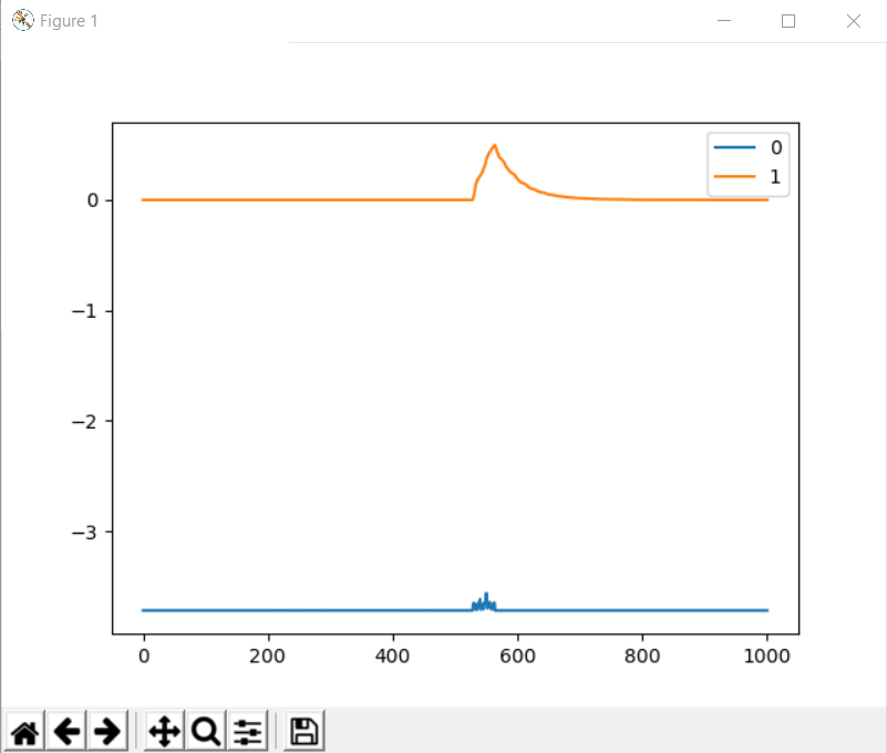
spi_error_rate is orange, pos_estimate is blue. 0.5 is the new bomb-out threshold for the spi_error_rate, so once the orange line gets higher than that the Odrive errors out.
I did not think to take a screenshot of the calibration cycle immediately after the ferrite ring installation, because I did not expect this to happen. But the graph then showed spi_error_rate as a completely flat line.
I can’t, obviously, reproduce the behaviour, because if I could this wouldn’t need an explanation.
Has anyone ever seen anything like this before? Does anyone out there have any ideas at all?


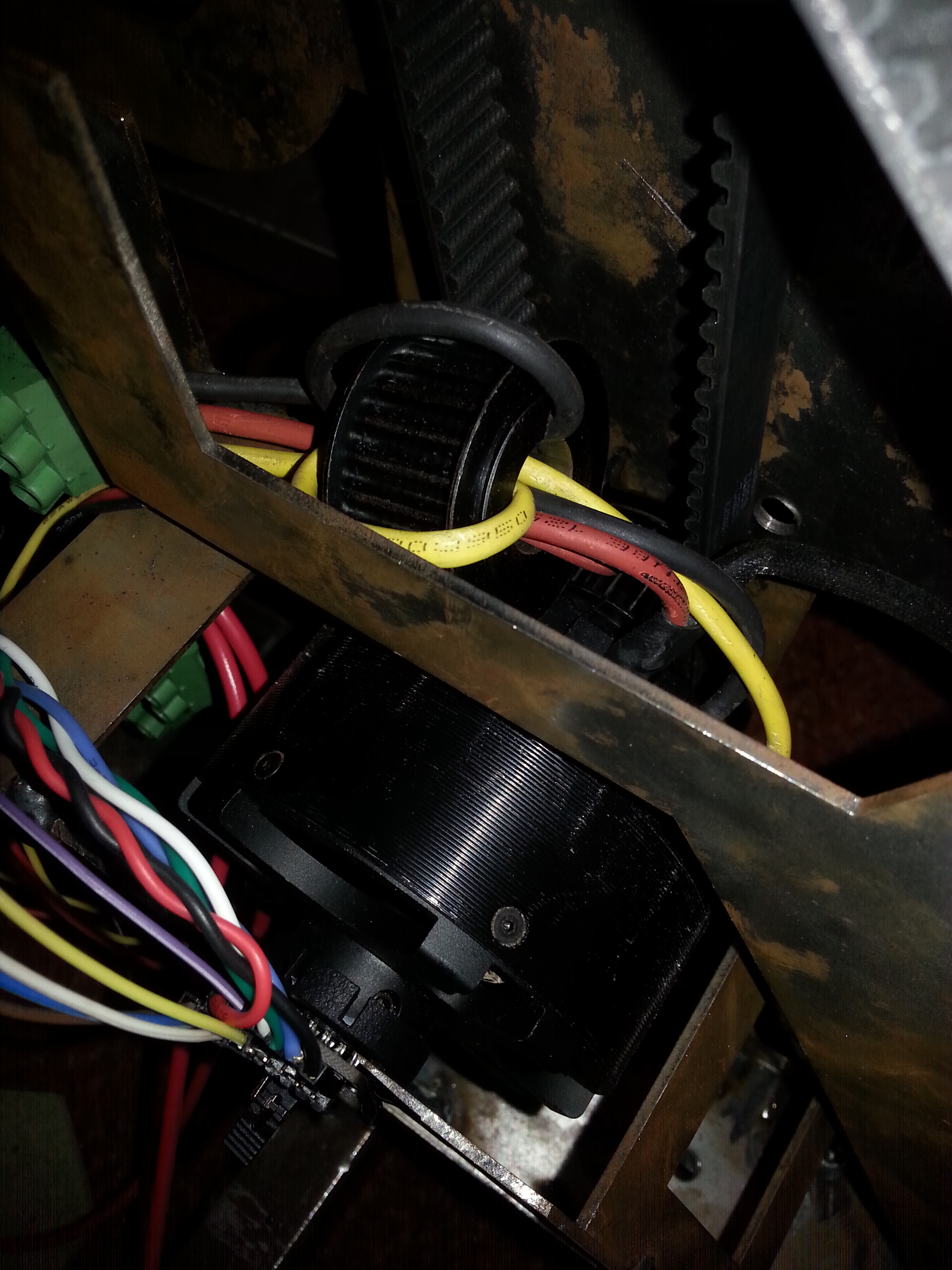
 ) on the three power leads to the motor. Is that where they are? They should be on the SPI lines.