Ok, here it is: Add ignore_abs_ams_error_flag by hbuhle2s · Pull Request #563 · odriverobotics/ODrive · GitHub
1 Like
An update to this: Ignoring the errors does indeed help (I haven’t tried Graham’s code, but I put in my own change):
-- if(spi_error_rate > 0.05)
++ if(spi_error_rate > 0.5)
could maybe do with a variable spi_error_tolerance or something.
The other thing that has helped a LOT is to run the AS5047p on 3.3v instead of 5v.
The only reason I can think of for this to make such a difference, is if there is a lot of noise on ODrive’s 5V rail.
So far I have not moved the resistor for 3.3v either - it seems to work fine regardless.
I have come back to this and I’m getting some really weird behaviour.
I have been using incremental mode for a while now with no problems at all (that I can see) so I’m pretty sure it’s specific to this SPI problem.
I am currently unable to run the AXIS_STATE_FULL_CALIBRATION_SEQUENCE all the way through because spi_error_rate jumps too high. So I have followed all the suggestions I could find on this thread and others to try to reduce noise.
To be specific, I have tried
- using 3.3V instead of 5V, making sure to use the same header as the SPI wires use.
- putting resistors in series with the SCK line. (I tried 10R and 100R, only having one of each, and not having anything between 20R-50R.)
- disabling the error bit check in the firmware as @grahameth did.
- increasing the
spi_error_ratethreshold to 0.5 as @towen did. - replacing the five SPI wires with fatter cables, and braiding them together.
- improvising a ferrite ring and wrapping the motor cables around it.
- tying the metal chassis to ground
What I’ve noticed as I was trying these is that for a few moments, each change would appear to be an improvement. Then, all of a sudden, that improvement would be ‘undone’.
This was especially noticeable with the ferrite ring. There, the error rate fell to pretty much zero. It stayed that way for one or two first-halves of a calibration cycle (which wasn’t finishing due to an unrelated config error I found and fixed.)
But then, all of a sudden, it was as if everything suddenly went back to its pre-ferrite-installation behaviour. Ie - the error rate shooting up straight away and the calibration cycle erroring out with ENCODER_ERROR_ABS_SPI_COM_FAIL
I had made no changes at all to cause this. I was simply running odrv0.axis0.requested_state = AXIS_STATE_FULL_CALIBRATION_SEQUENCE followed by dump_errors(odrv0,True) over and again, just as I had been before.
Then I tried it again after a ten minute pause, and found that it “worked badly” for one single run, then resumed not working at all after that. By “working badly”, I mean the spi_error_rate got worse and worse, but at a slower rate than it had been. By not working at all, I mean the spi_error_rate shoots up over the threshold straight away.
Further testing confirms that I can reliably get one single bad half-run, if I wait ten minutes after the last failure, and any subsequent tries (without waiting) end in immediate failure.
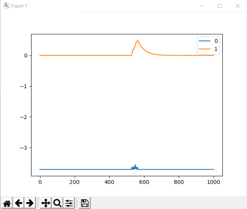
Here is a screenshot of the “bad but trying” calibration run: (Sorry for the poor quality.)

spi_error_rate is orange, pos_estimate is blue. 0.5 is the post-@towen bomb-out threshold for the spi_error_rate, so once the orange line gets higher than that the Odrive errors out. I don’t know why the pos_estimate is glitching out like that, unless comms noise is able to do that.
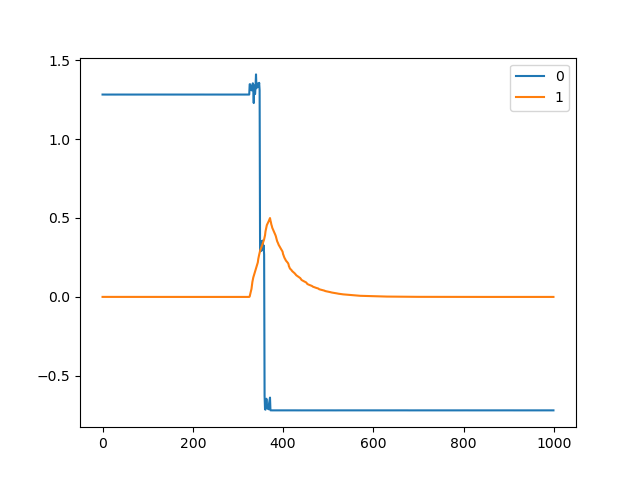
Here is a screenshot of what you get every time, if I run the calibration cycle again without waiting for ten minutes:
Sometimes the pos_estimate glitches - the pedals barely twitch but it reports a large turn:
Does anyone have a clue what might be going on?
Immediately after installing the ferrite ring, that orange line was totally flat, and now suddenly it’s acting like this. I am doubting my sanity here.
Is this the most robust way to improve SPI encoder to work? So far i did a few experiments. but i think i come to the conclusion that it is a “DON’T”.
1 Like

Here’s the video from the OpenDog creator. He uses AS5047 SPI Encoders on his robot with no issues at all. I asked him in the comments how he was able to acheive this, and he said that there’s nothing special, he just followed the ODrive documentation and it just works. What are we doing wrong?
1 Like
I made a few tests and it seems to work with AS5047P in SPI.
I made my own board, photo and desctiption are here. I use two AS5047P encoders powered by 3.3V. First one is connected to axis0 to drive the motor, second is connected to axis1, which is not present on my PCB, but firmware reads it’s values correctly. I made this to read absulute angle after reducer to avoid homing in my robotic arm project.
I made two firmware modifications: disabled AMS error bit check and increaced max spi_error_rate to 0.1.
During idle state spi_error_rate floats around 0.007, but when mosfets engages (motor calibrtion, encoder calibration and closed loop mode) spi_error_rate drops to 0.005. It’s really wierd behavior, and it should be vice versa, but it works. I made few tests with 500W milling spindle motor, which has 2 pole pairs, and there were no issues in velocity and position control modes. I can post my further tests, if someone is interested.

Do you have ferrites on your motor wires?
Are there any series resistors in the SPI wires? (this is to prevent ringing seen in my post above: Clarification on SPI Encoders - #21 by towen)
If you are making your own boards though, I would highly recommend that you use a pair differential RS422 transciever chips if you are wiring the encoder off-board.
If the encoder is on-board, then it shouldn’t be an issue though.
Still use the ferrites, they help in all cases.
Spi isn’t really meant for this, it’s an on-board bus, not meant to go over wires.
I didn’t see a mention of the speed you’re trying to run it with but turning the speed way down usually results in better stability.
Also if you’re running it over a power supply instead of a battery, the switching noise will usually cause spi issues.
2 Likes
No, I don’t use ferrites on the motor wires and resistors on SPI. The issue with spi_error_rate occured way before I was able to power the motor. Anyway, motor cables will be too short to put ferrites on them.
It shouldn’t. There is DRV8301, which converts input voltage to 5V, then there’s LDO (I use low noise TI LP2985AIM5-3.3), which drops voltage to 3.3V and filters out any noise.
Why? ODrive firmware uses 2.625 MHz, which does not seem too high. SPI signals are push-pull on all ends, so there shouldn’t be a problem with signal edges. LCDs with SPI controllers like ILI9341 uses 10+ MHz clock speed with no issues, even when connected with long dupont cables.
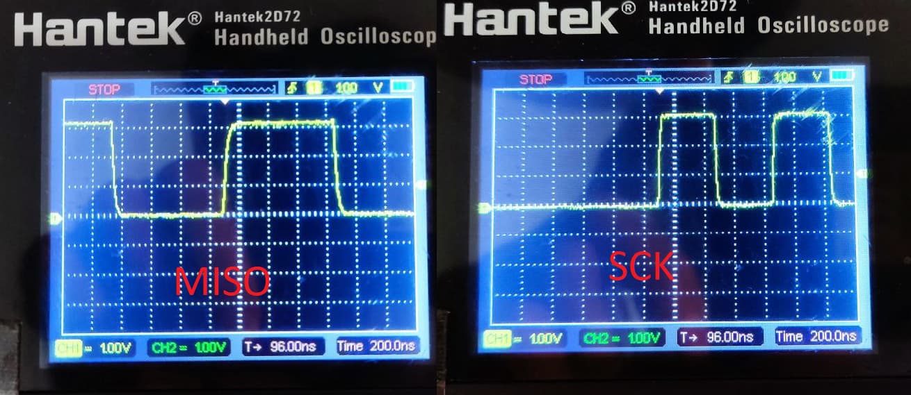
I soldered longer unshielded cables (about 300 mm) and captured MISO and SCK at the encoder side, edges seem to be fine.
1 Like
- The ODrive’s large switching currents get coupled to the SPI, ferrite rings will reduce this dramatically.
- Make sure you’re using appropriate pins for SPI. I recommend GPIO 7 and 8
- Depending on the exact encoders you’re using, they may not tri-state properly.
I wasn’t aware of any differences in the GPIO pins. What’s special about 7 and 8?
I think PKav said that his motor is so close to the board that he couldn’t fit a ferrite. But TBH I agree even with wires that short, a ferrite should help.
7 and 8 aren’t assigned to the UART, for example 
1 Like
SPI is a push-pull bus, there shouldn’t be any problems with such low freqency. I used to run SPI LCDs at 40 MHz with no issues at all.
GPIO 7 and 8 has filtering capacitors. But if it’s nCS line, there’s nothing to filter.
The main point is that spi_error_rate does not correspond to anything. It’s meant to show incorrect data rate, but shadow_count or pos_spr_counts does not show any deviation at all. Even if one bit would be corrupted by noise or anything else, pos_spr_counts or shadow_count would show really weird value, but these counters always show correct values. I guess, there’s something wrong with firmware. I’ll debug it soon and post my investigation here 
BTW, what happened with this commit? Why was it deleted?
I’d like to know that too (I made that PR). My guess is that it’s too much of a hack.
Invalid encoder readings are not added to shadow_count, so you wouldn’t see that there. But even if it was, in my experience the received values are always solid, even if the error flag is checked.
No, the spi_error_rate is the proportion of data packets from the encoder that are erroneous. It is a running average of an error flag i.e. a value of 1.0 would mean that all packets are wrong and then you’d expect to have no updates at all to shadow_count etc. and a value of 0 means everything is normal. A value of 0.3 means that 30% of the time, either the SPI transaction did not complete at all, or the error bit was set, or the CRC failed (if there is one, i’m not sure if there is)
I meant there seems to be something wrong with software. There is CRC and error bit check. I removed error bit check, and spi_error_rate is still not 0, but everything works. And I assume it’s not noise because:
- I checked signal edges at both sides with osciloscope and they’re fine. No noise, no ringing. Photo is in the above post.
- There is DRV8301 on the same SPI bus. Noise would have eventually disturbed it’s communication, but I’ve never got ERROR_DRV_FAULT on this axis.
- Switching motor to Closed loop and back to Idle does not influence spi_error_rate as it “should”.
I will try to debug it and, probably, find a solution. I prefer to develop for STM32 with MDK Keil, so it will take time to switch to VS Code and those GNU compilers…
1 Like
Are you positive you have an AS5047P? If you have an AS5047U, for example, there is no error flag, just a redundant parity (iirc), so you’d see something like 50% error rate.
Yes, I currently have AS5047P.
I’ve also tried AS5047D and AS5048A. They all behave same way in SPI mode.
So, I guess, I managed to make SPI Encoder work.
I am using 2 AMS5047P, one for each axis.
First of all, I had increaced SPI baud rate by factor of 2. Yes, increaced, it’s 2.625 MHz for encoders too, not just for DRV8301. The reason for that was that on 1.3125 MHz SPI bus sometimes was not able to update both encoders in time, it was counted as error and added to spi_error_rate. It’s line 48 in encoder.cpp:
.BaudRatePrescaler = SPI_BAUDRATEPRESCALER_16,
I also lowered maximum allowed spi_error_rate by factor of 10. It’s line 737 in encoder.cpp:
if (spi_error_rate_ > 0.05f) {
I did not remove 14th bit check. According to datasheet, it’s not error flag, it’s just always stays 0. And it helps to diagnose disconnected encoder cable 
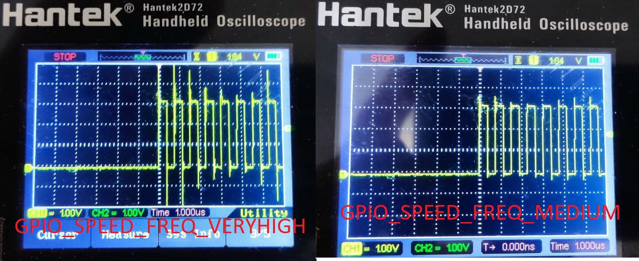
I also recommend to change slew rate for SPI pins. It is set to “Very High”, which causes lot of ringing. “Low” or “Medium” is more than enought for 2.625 MHz. It’s line 107 in spi.cpp:
GPIO_InitStruct.Speed = GPIO_SPEED_FREQ_MEDIUM;
That’s it. Now spi_error_rate stays below 0.001 and everything works. It was tested on my custom PCB and on the genuine ODrive v3.6-56v (or, maybe, not genuine, I don’t know where it came from, but it seems to be genuine).
4 Likes
Thanks for the update (and the slew rate measurements)! I’ve compiled these changes into a pull request. https://github.com/odriverobotics/ODrive/pull/661