Clarification on SPI Encoders

We made a mistake when we released 0.5.1, I built it from 1 commit beyond the tag and it got labeled “dev”. So it’s probably the 0.5.1 release code.

@jbombastor People have all sorts of problems with this dev board, I suggest doing a forum search because this problem has been solved a dozen times over

@Wetmelon How do you even do a forum search on here? I see no search bar anywhere. The “all categories” selector box gives you a search box that only seems to work with category headings. Previously on creating New Post it would try and find similar posts for me, but I’ve just tried it now and it either doesn’t come up or produces unhelpful results.

((EDIT: worked it out. Once it was dark outside, my monitor was bright enough for me to see the dim search icon in the top right corner. I can’t stop and look now but I will come back and see if it throws up any results that weren’t on Google.))

I had already read every post from here that Google would show me before posting. Most of what I found didn’t apply to the symptoms I’m getting, and most of the posts I read did not end in the problem being solved.

As a newcomer who doesn’t yet have the experience or know all the jargon, it’s quite possible I could have missed some important details because I didn’t know what to look for.

But I’m sure even I would have noticed if my problem had been solved a dozen times over.

If there is some resource I’ve missed, can anyone tell me where it is?

And, if this board is such a troublemaker, can the devs recommend one they know will actually work? Or are they all like this?

I assume from your response that the firmware on my ODrive is probably identical to the latest release, and so it’s safe to dfu update it. I’ll also assume that the ODrive can probably be trusted and the problem is with the encoder board.

1 Like

A few more findings, posted here for completeness:

One chap posted on a different post that you need to tie the TEST pin to ground. (I don’t understand why you would, and there was no explanation given.) But I did that anyway, and now I get this result, which is subtly different from what I had before:

In [31]: odrv0.axis0.encoder
Out[31]:
error = 0x0000 (int)
is_ready = False (bool)
index_found = False (bool)
shadow_count = 0 (int)
count_in_cpr = 0 (int)
interpolation = 0.5 (float)
phase = 0.0013422966003417969 (float)
pos_estimate = 0.0 (float)
pos_estimate_counts = 0.0 (float)
pos_cpr = 0.0 (float)
pos_cpr_counts = 0.0 (float)
pos_circular = 0.0 (float)
hall_state = 7 (int)
vel_estimate = 0.0 (float)
vel_estimate_counts = 0.0 (float)
calib_scan_response = 0.0 (float)
pos_abs = 0 (int)
spi_error_rate = 0.0 (float)
config:
  mode = 257 (int)
  use_index = False (bool)
  find_idx_on_lockin_only = False (bool)
  abs_spi_cs_gpio_pin = 3 (int)
  zero_count_on_find_idx = True (bool)
  cpr = 16384 (int)
  offset = 0 (int)
  pre_calibrated = False (bool)
  offset_float = 0.0 (float)
  enable_phase_interpolation = True (bool)
  bandwidth = 1000.0 (float)
  calib_range = 0.019999999552965164 (float)
  calib_scan_distance = 50.26548385620117 (float)
  calib_scan_omega = 12.566370964050293 (float)
  idx_search_unidirectional = False (bool)
  ignore_illegal_hall_state = False (bool)
  sincos_gpio_pin_sin = 3 (int)
  sincos_gpio_pin_cos = 4 (int)
set_linear_count(count: int)

So we now have a hall_state, an interpolation and a phase. Although none of them do anything and pos_cpr still stays at 0 when I move the motor by hand.

However, now it actually lets me run odrv0.axis0.requested_state = AXIS_STATE_FULL_CALIBRATION_SEQUENCE

Unfortunately the result is an immediate ENCODER_ERROR_ABS_SPI_COM_FAIL. But still, it’s a result to report.

After that I tried to swap back to ABI mode, which never worked either. That didn’t work and gave me the error message ENCODER_ERROR_NO_RESPONSE when I ran AXIS_STATE_FULL_CALIBRATION_SEQUENCE.

I’m now going to wire the encoder board up to an arduino and see if I can see the ABI outputs changing onscreen when I move the motor by hand.

Well that’s answered one question. On wiring it up to the arduino, all three outputs (ABI) are high all the time, and the chip quickly gets hot to the touch. I guess it’s fucked somehow and I’ll have to buy another one.

I have no idea what would have caused that, but the first ODrive I bought did the same thing.

If it’s not throwing that error when IDLE but throws it when trying to calibrate, you have the classic SPI noise error, which is good because you’re making progress! Use short (< 6") SPI lines, use 50 ohm series resistors, shielded cable, or better yet - use shielded twisted pair over a differential bus (you have to add RS422 transceivers at both ends). Also, use the ferrite rings (available here) Personally, I don’t recommend SPI without differential, as it’s just too much trouble, unless you have EXTREMELY short wires.

I will be testing a differential encoder solution this coming week, so you may be able to get a known working solution directly from us shortly.

That’s news to me… I have seen a lot of threads about problems with the AS5047p but I fail to find one with a solution.

interesting re. the differential transievers! Although I am struggling to make it work even with wires <10cm - it’s infuriating because as I say, it used to work fine over several metres of cabling.

The first issue seems to be that there is a lot of ringing on the clock signal SCK - and it is coupling onto the MISO and MOSI lines. I guess that has to be wiring - I’ll try adding 50R series resistors.

SCK: (motors are off)

MOSI: (motors are off)

MISO: (motors are off)

The second issue is that despite a ferrite on the motor wires, inverter switching noise is being coupled to all of the lines. The effect of that seems to be to throw the chip into some sort of ‘sulk’ state, where it sets its error bit high and keeps it there until a power cycle of the encoder itself.
This only happens when the motor is on, and it happens more quickly when the VBus voltage is higher. Above 20V it drops out in about 1 minute on average - above 30v it drops out in 10 seconds or so.

I can’t see how adding series resistors would help with this second issue.

No error (note the bit at the cursor is low - that seems to be the error flag):

If I turn on PWM (torque mode, zero demand) then I see a nasty ringing on both lines:


Then eventually the error bit gets set until I reset the power (clear errors or odrv0.reboot is not enough) .

Interestingly, the position data is still there, but it is now being ignored by the ODrive.

Now if you thought that was weird, here’s where it gets REALLY weird.

I have another AS5047p dev board on a different motor. This one has a 30cm cable with a connector (whereas the other one had a 3 metre cable with the same connector). Both cables are CAT5, with power/GND on a pair, MOSI/GND on a pair, MISO/GND on a pair, and SCK/CS on a pair.

I also have a 3 metre extension cable with the same connectors, also CAT 5. These cables used to work perfectly reliably, and are not damaged in any way as far as I can see.

If I plug my motor with the 30cm cable directly to the ODrive, immediately the error bit is high and stays there.
but if I move the motor a bit (it’s not on) then the encoder goes into a “super-sulk” state, and doesn’t just set the error flag, but returns a position value of 0 at all times until I reset the power.

Super sulk:

Now here’s where it gets weirder: if I connect my 3 metre extension cable, it improves things: It still sets the error flag, but doesn’t enter the super-sulk state.

Maybe the extension cable is acting like those 50R resistors… I will try those next. :joy:

But again - this used to work 100% reliably! - wtf has changed??

EDIT: now it is not even setting the error flag, so long as it is on the long cable. So it’s behaving the same as the other motor - it works until I enable PWM.
But again, both of these motors worked fine all the way up to 55V, for weeks on end, about a year ago.

:confounded:

Also, there is a third state where the encoder doesn’t stay ‘sulking’, but sets its error bit randomly, so that spi_error_rate is between 0.5 and 1, depending on the motor’s position.
I can’t see how this can be anything apart from a faulty sensor. Please correct me if you can think of any other reason for this!

In the plot below, I have set the livepplotter up as follows:

        # If you want to plot different values, change them here.
        # You can plot any number of values concurrently.
        cancellation_token = start_liveplotter(lambda: [
            my_odrive.axis0.encoder.count_in_cpr/16384.0,
            my_odrive.axis0.encoder.spi_error_rate,
        ])

Blue is count_in_cpr / 16384.0 and orange is spi_error_rate.

I am moving the motor by hand.
The encoder appears to read either zero or 16379 (and set its error flag) over half of its operating range. The remaining part of the range seems ‘normal’-ish, except spi_error_rate tends to 0.5 instead of 1. This is with the 3m extension cable.

I can see from the scope though, that the error bit is being set about 50% of the time all the time (not just in certain positions) but at certain times (when most of the bits are 1) there are weird glitches where MISO spikes low briefly, at a much higher frequency than the clock.

I can’t explain this. It’s either a fault with the chip, or maybe the chip is responding to some noise on the clock that I can’t see on the scope.

:confounded:

I’m not sure how the SPI pins are setup, but maybe the default GPIO state for that pin has been changed? It might be using a pull-down resistor where it previously wasn’t or vice-versa?

I think changing a GPIO state requires a save_configuration and reboot.

[quote=“Riewert, post:24, topic:6451”]
I’m not sure how the SPI pins are setup, but maybe the default GPIO state for that pin has been changed? It might be using a pull-down resistor where it previously wasn’t or vice-versa?

Hmm, is this configurable in software or do I have to go to CubeMX to see that?
I’d be surprised if anything had changed regarding SPI config though, because the DRV8301 gate drives are on the same SPI bus

The “fixed dozens of times” specifically refers to the jumper setting on the AS5047P development board that @jbombastor is using, not necessarily SPI.

Good question. I also noticed something changed around the time between Tobin’s branch and 0.5.1, but when we look at the data it looks sorta fine. We did create an SPI arbiter in that time, and I think some GPIO settings changed but it definitely works (at least on devel). I’m going to link your post and nice oscilloscope traces to @madcowswe , @Samuel , and @PJohnson. They may be able to run some tests.

1 Like

Thanks @Wetmelon :slight_smile:

@jbombastor after hijacking your thread I at least ought to reply to you.

I heard that the ODrive v4 will use a SPI magnetic encoder chip on board, but from a different manufacturer. MPS instead of AMS. MA732 if I remember correctly.
Maybe the AMS ones are just crap. (I would love for someone from AMS to comment on this)

There are also RLS and CUI who make these same type of sensor.

You smoked the encoder, your arduino, your oDrive or all three? :frowning:
I’m not sure how you can have done that with an AS5047p… maybe a ground loop? There are some good threads on here about what those are and how to avoid them.
Avoid connecting the encoder to anything else except the oDrive - that includes the chassis. Maybe a screw touched a PCB trace?

For the above tests I was using a recent devel from maybe 3 weeks ago at the most…
I tried to repeat with the most recent obe, but ran into an issue (see Failed to flash firmware using odrivetool from latest devel)

Just the encoder. A previous Odrive died while that same encoder was plugged in, so my working theory is that it took it with it.

That could potentially mean everything I’ve done since the start of this thread was with a damaged bit of kit.

Anyway, I’m now waiting on a new one to be delivered and am out for the count until then.

Ok, now that DFU is working, I have updated my firmware to the latest devel

Unfortunately, I get the same issue.
After a few seconds (without any PWM enabled) I immediately get ENCODER_ERROR_ABS_SPI_COM_FAIL - nd on the scope I can see that the encoder has set its error bit, but is otherwise returning an apparently valid position.

In [7]: odrv0.axis0.encoder.spi_error_rate
Out[7]: 0.5088629722595215

Liveplotter as before, while turning the motor by hand:

Looking at this, It’s almost as if the ODrive is reading the MSB of the data and interpreting it as the error flag?
But then if that were the case, then I wouldn’t get spi_error_rate=0.5 in any position except right on the MSB boundary.
So it’s more like it’s interpreting (MSB + LSB) as the error flag… ??? :confounded:

Tom, are you able to build the firmware from source?

If so, can you check if this fixes the problem? It’s in encoder.cpp, line 566. If not, I can build a version and send it to you.

image

1 Like

Hi Wetmelon,

Unfortunately, no. It seems to make no difference. :frowning:
Liveplotter trace: (turning motor steadily by hand anticlockwise)

This is my full diff from latest devel:

diff --git a/Firmware/MotorControl/encoder.cpp b/Firmware/MotorControl/encoder.cpp
index 2dcb70ba..95dd122b 100644
--- a/Firmware/MotorControl/encoder.cpp
+++ b/Firmware/MotorControl/encoder.cpp
@@ -563,7 +563,7 @@ void Encoder::abs_spi_cb(bool success) {
         case MODE_SPI_ABS_AMS: {
             uint16_t rawVal = abs_spi_dma_rx_[0];
             // check if parity is correct (even) and error flag clear
-            if (ams_parity(rawVal) || ((rawVal >> 14) & 1)) {
+            if (ams_parity(rawVal & 0x7FFF) || ((rawVal >> 14) & 1)) {
                 goto done;
             }
             pos = rawVal & 0x3fff;
diff --git a/tools/odrive/utils.py b/tools/odrive/utils.py
index 73489130..75e52783 100755
--- a/tools/odrive/utils.py
+++ b/tools/odrive/utils.py
@@ -133,7 +133,7 @@ def oscilloscope_dump(odrv, num_vals, filename='oscilloscope.csv'):
 
 data_rate = 200
 plot_rate = 10
-num_samples = 500
+num_samples = 5000
 def start_liveplotter(get_var_callback):
     """
     Starts a liveplotter.
diff --git a/tools/odrivetool b/tools/odrivetool
index 5d0e9776..4ad9e67a 100755
--- a/tools/odrivetool
+++ b/tools/odrivetool
@@ -157,8 +157,8 @@ try:
         # If you want to plot different values, change them here.
         # You can plot any number of values concurrently.
         cancellation_token = start_liveplotter(lambda: [
-            my_odrive.axis0.encoder.pos_estimate,
-            my_odrive.axis1.encoder.pos_estimate,
+            my_odrive.axis0.encoder.count_in_cpr/16384.0,
+            my_odrive.axis0.encoder.spi_error_rate,
         ])
 
         print("Showing plot. Press Ctrl+C to exit.")

For the sake of sanity, I tried commenting out the whole IF statement with the goto, and I got this:


It is as if there really is some flag that is set 50% of the time, and is corrupting the data.

I do have an ST-Link, would it be worth setting up a debugger? Or perhaps I will check my scope traces against the chip’s datasheet to see wtf it is really sending.

Also, I tried a second time (no changes except system power cycle including encoder) and I get this: (motor turning steadily clockwise by hand)

Since i’m getting variable results, I will remove my hack and try your code again, but I don’t think it’s going to work since clearly the position data is wrong.

OK, some progress, I think??

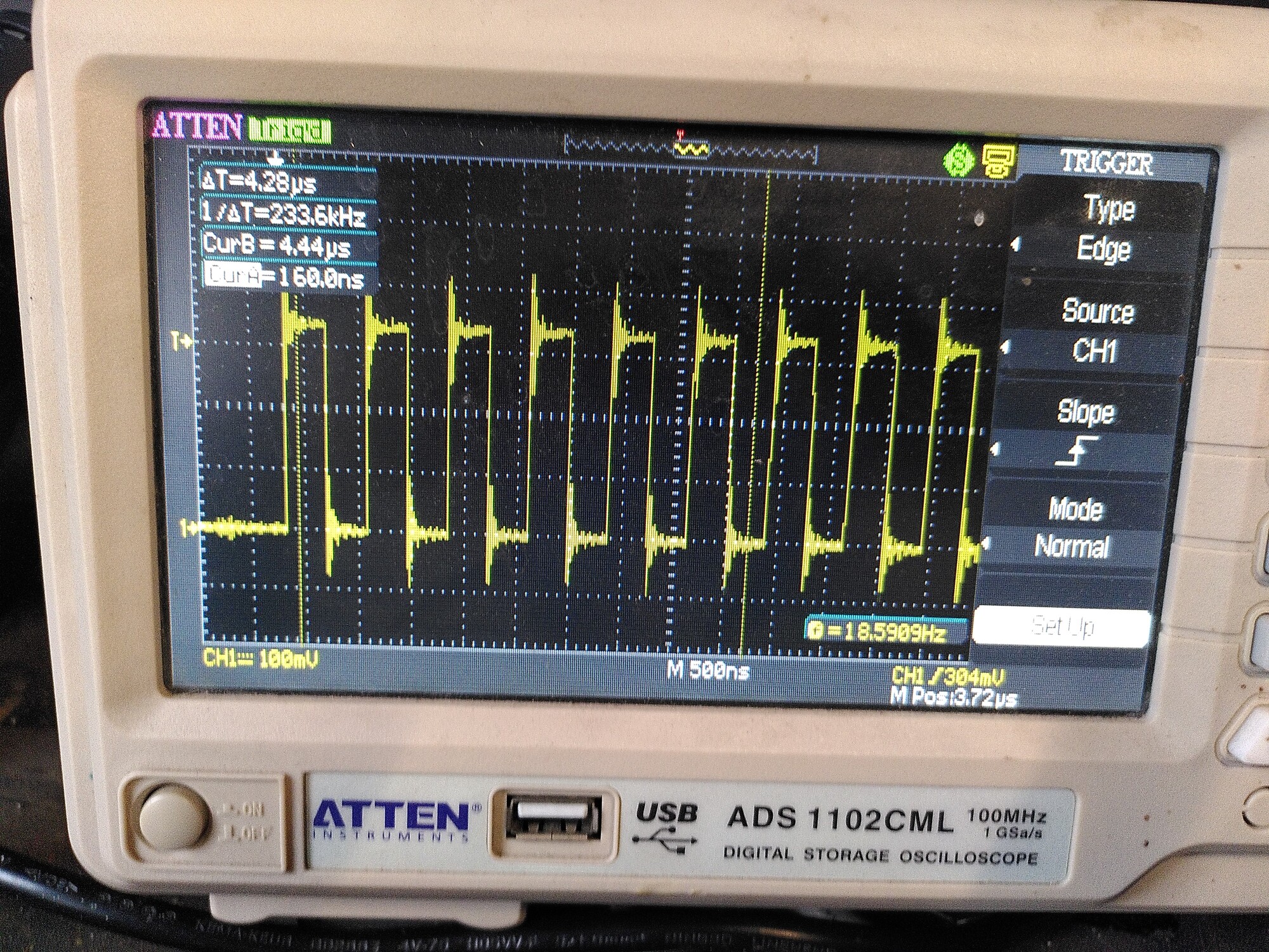
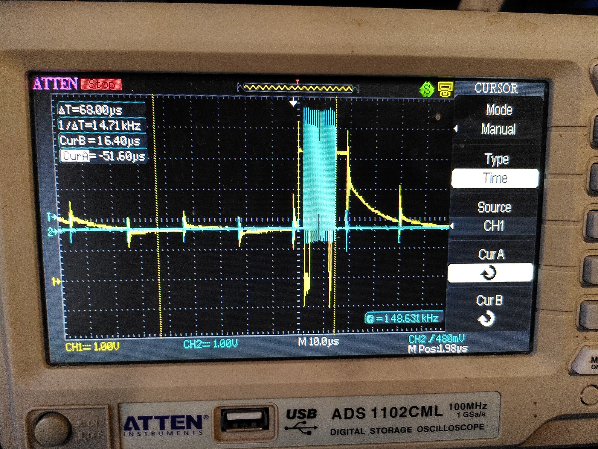
I went back to my scope, and I noticed that I was getting those bogus SPI transitions. The scope was ficking between two traces:

& .

I remembered about the 50R resistor. I didn’t have 50R to hand but I used 100R, and put it in what I thought was the SCK wire. Actually it was MISO.
That made a big difference. The position looks good now, although SPI_error_rate is still hanging around 0.5, in all positions.

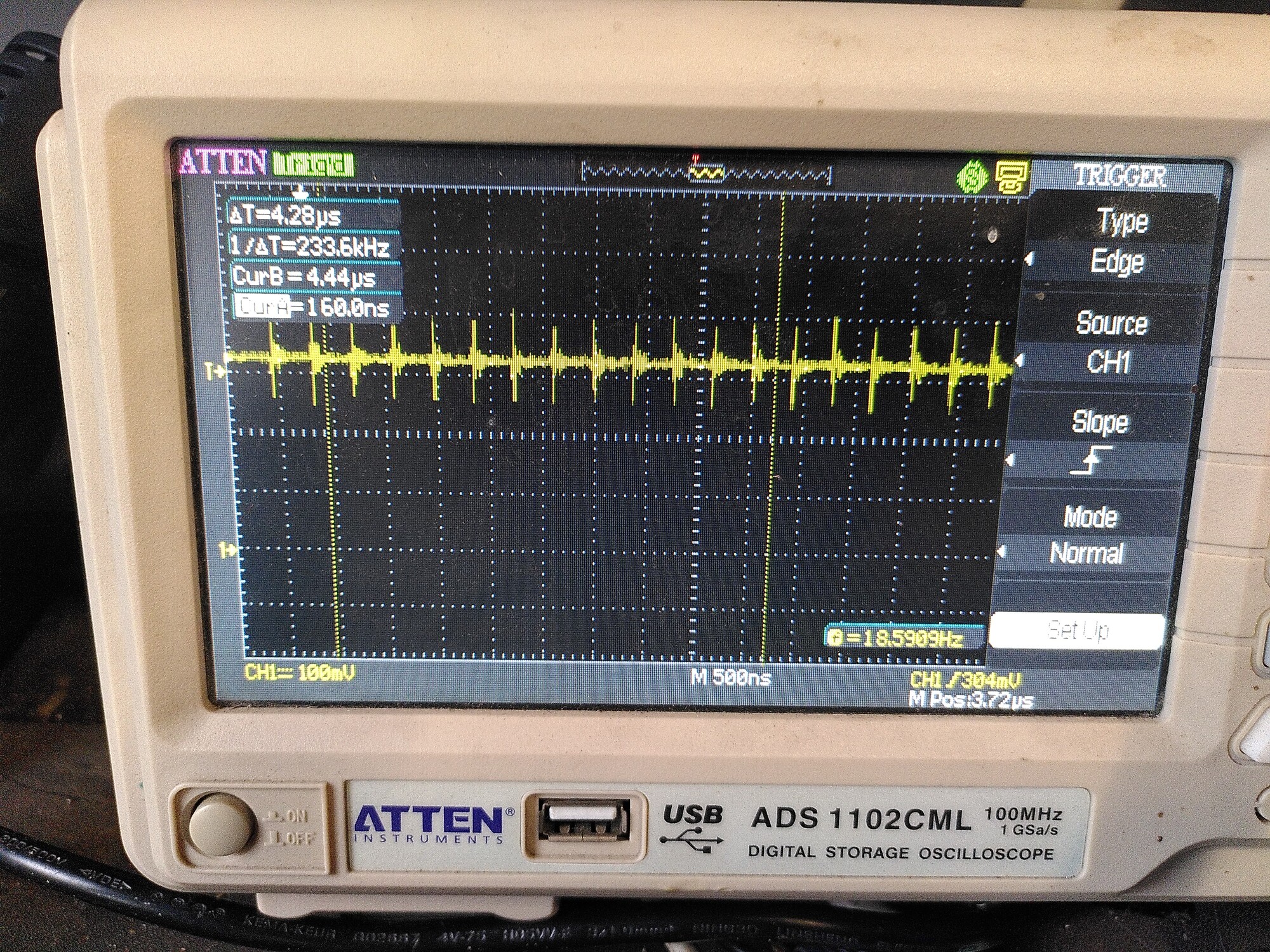
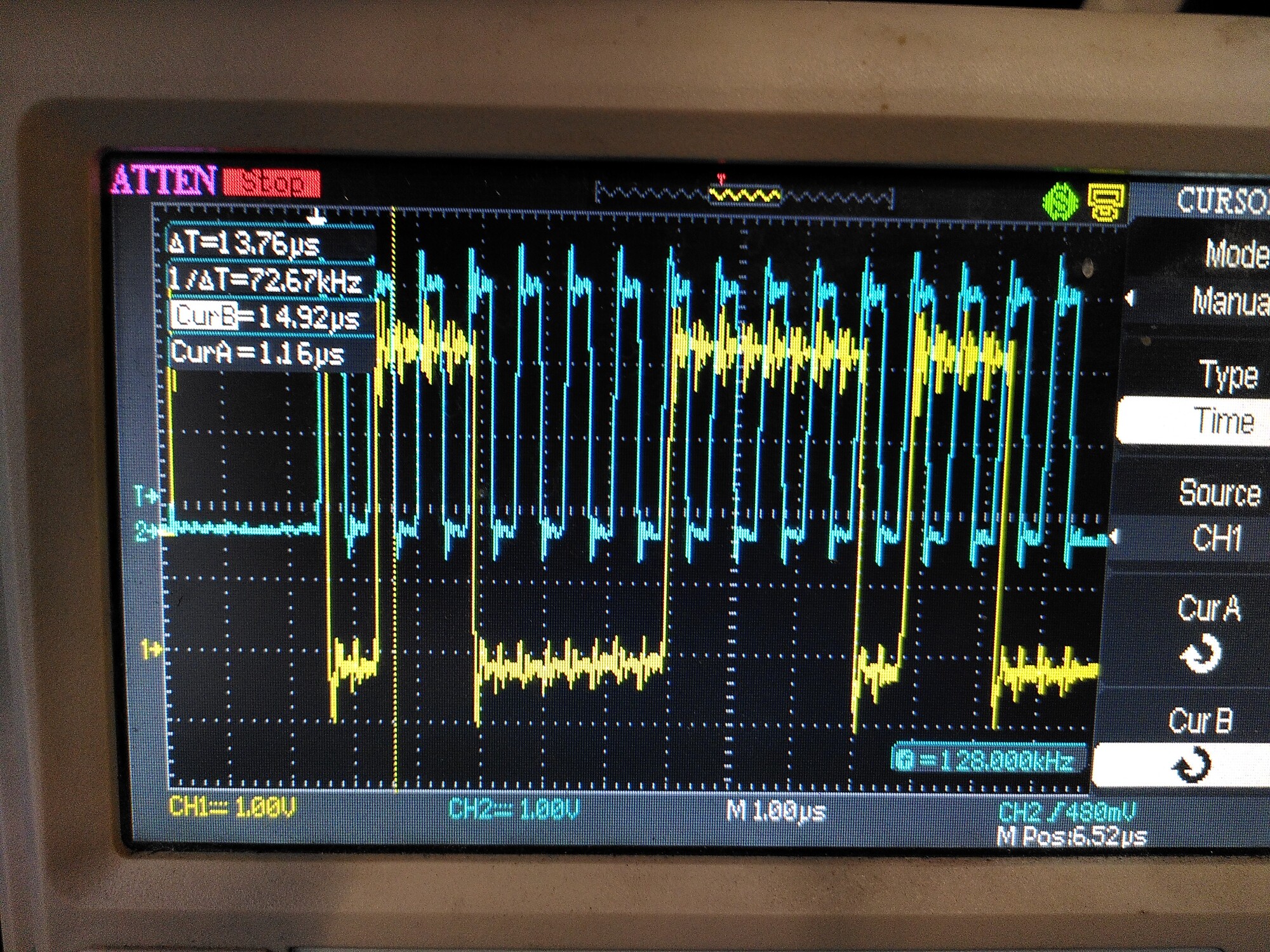
Then I thought OK, i’ll do the other wires, which is when I noticed my error.
So I put a resistor in line with SCK, and left the one I put in MISO.
That made things worse. :confused:
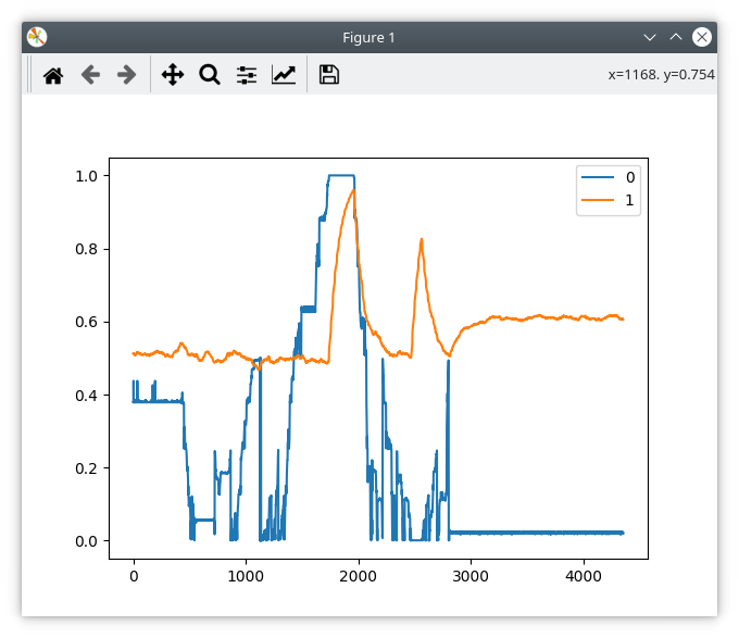
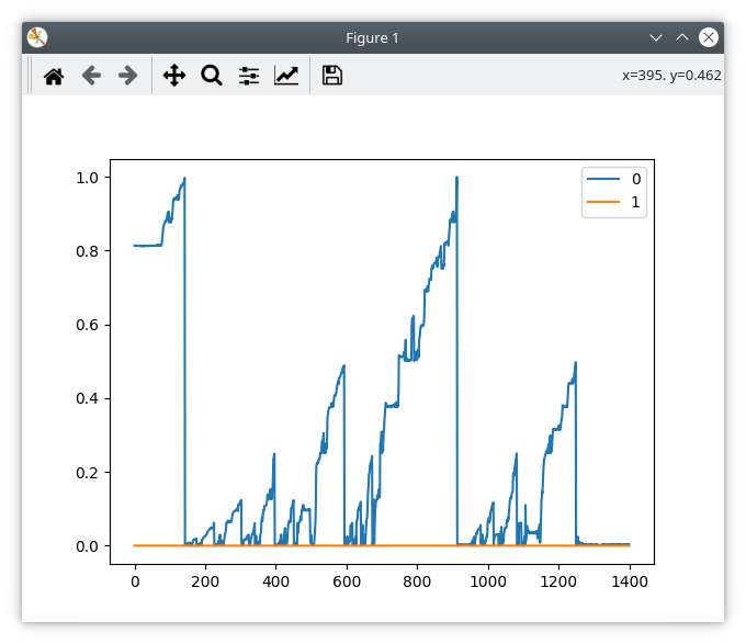
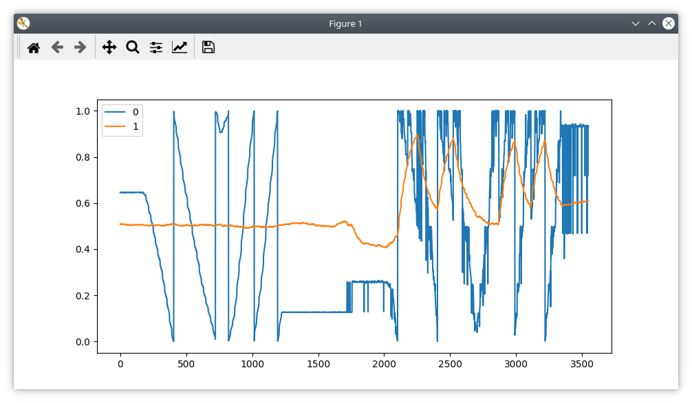
To illustrate, the plot below is with 100R in line with MISO on the left (the resistor on SCK is shorted out). The right part is where I remove the short, and put 100R in line with SCK.

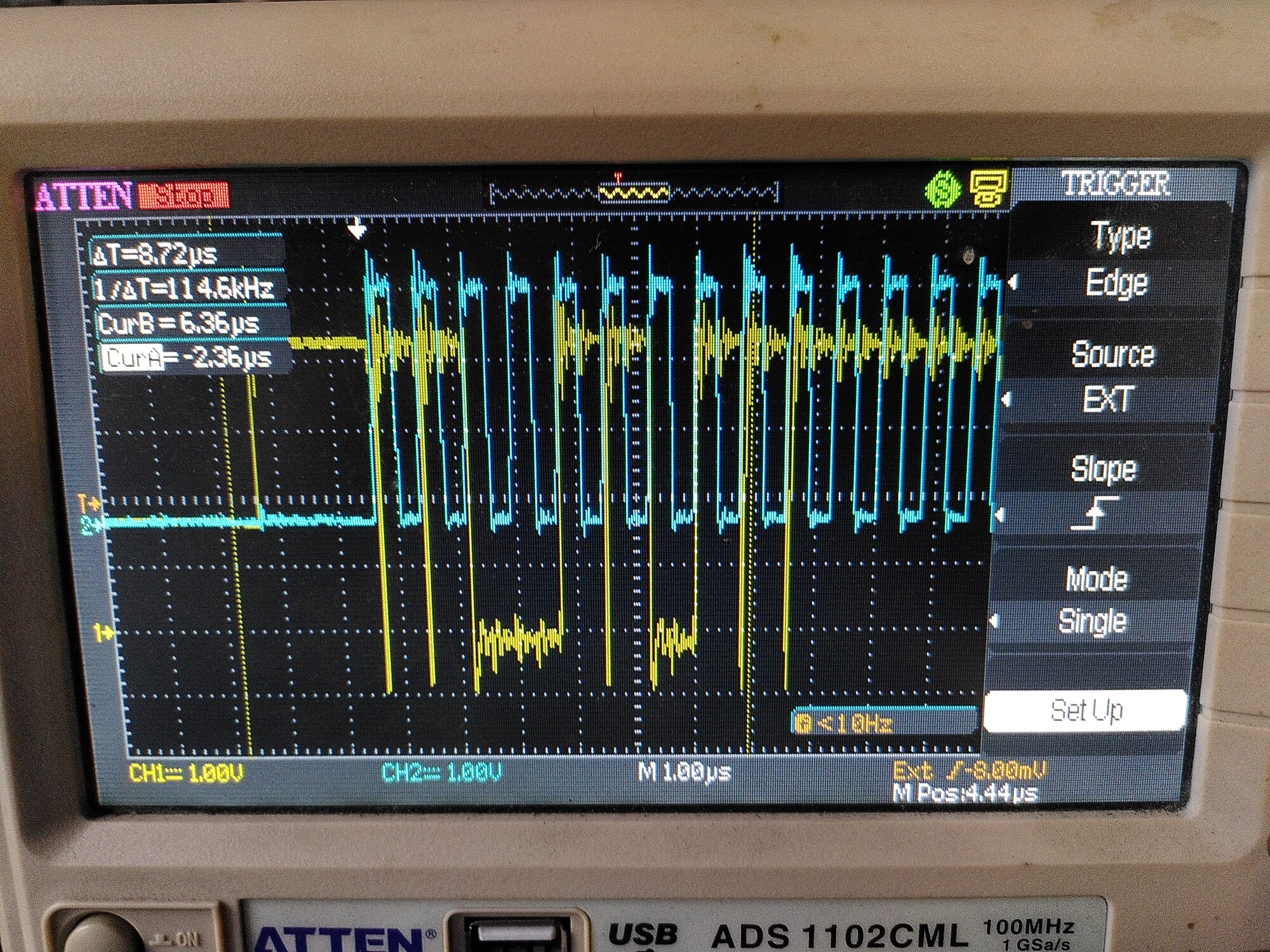
Interestingly, I can see the difference on the scope.

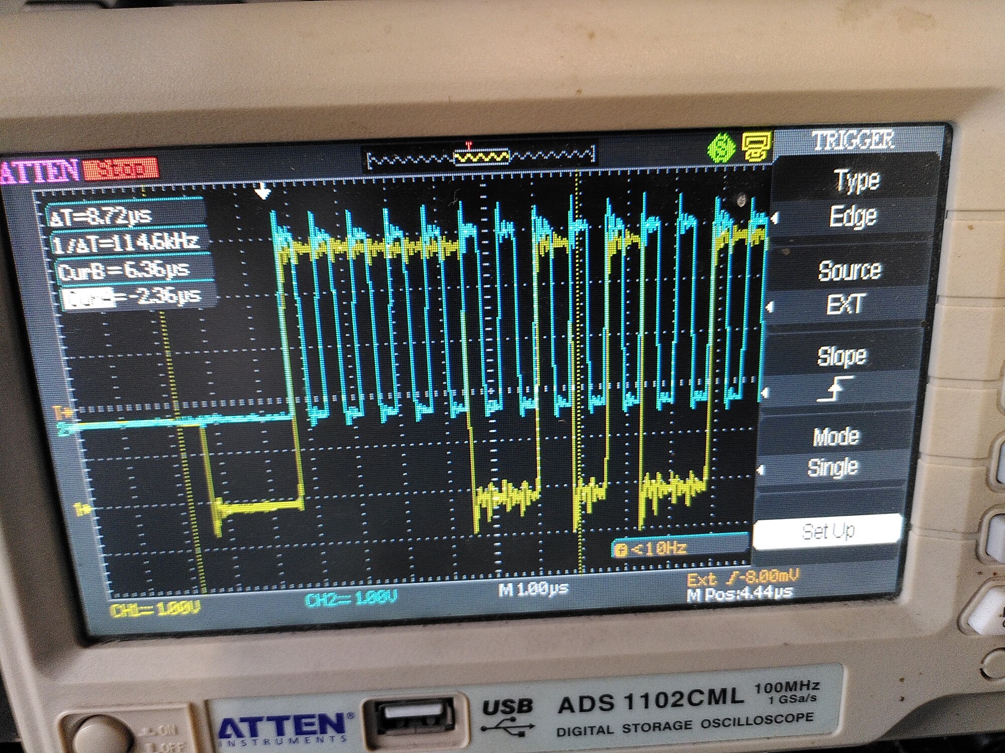
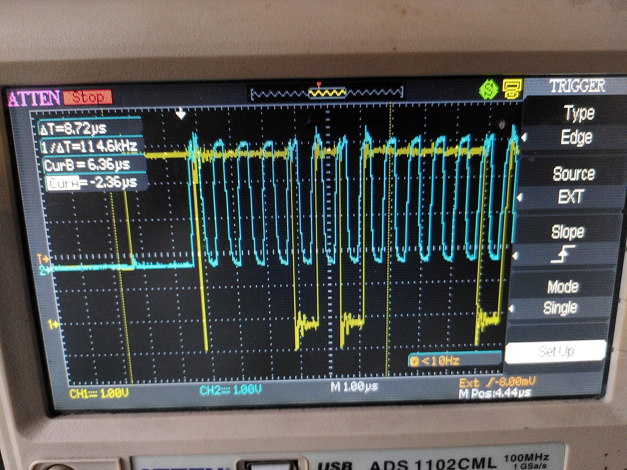
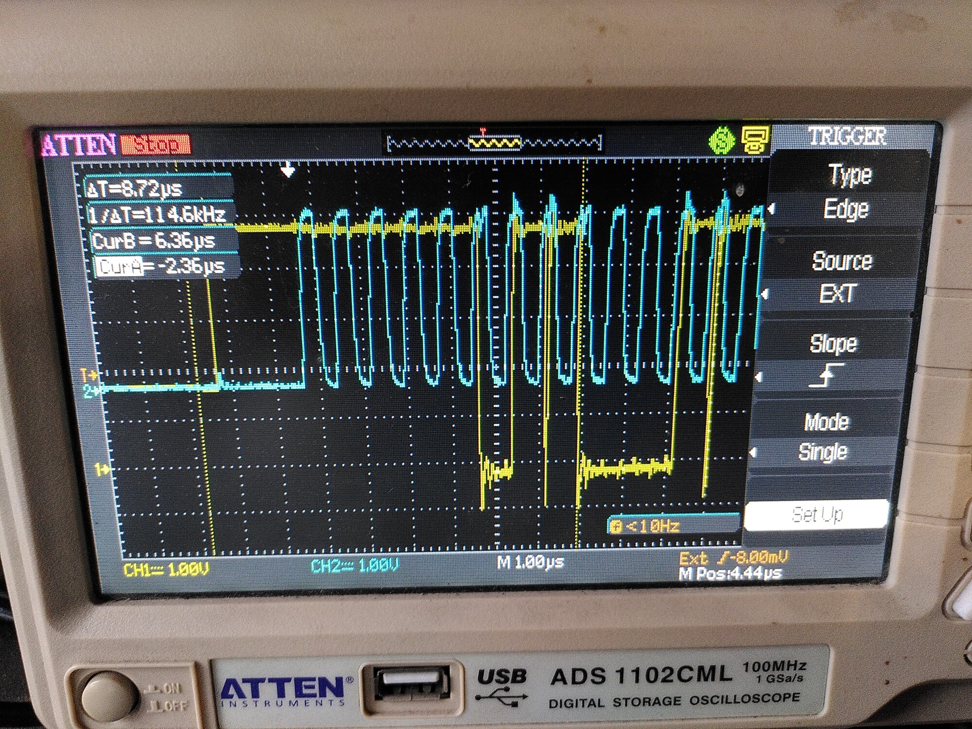
The first trace is with 100R in line with MISO (in yellow, but the probe is on the encoder side of the resistor) and no resistor on the clock (because it’s shorted out).
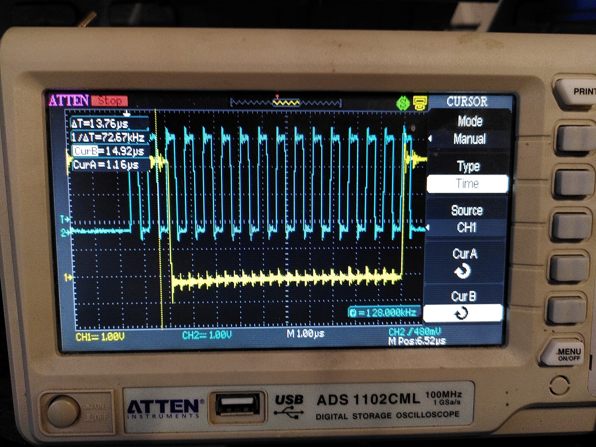
The other two are with the short removed, so 100R on the clock too.
You can see those weird transients appearing on the second and third trace.

Ill see if I can get hold of some of the recommended 50R and get back to you. :sweat_smile:

And no, I don’t think it was anything you did in the code that caused this - i’m pretty sure it still happens on your old RazorsEdge branch which is what I was using in 2019. It’s probably definitely maybe a SPI issue. But Why the pitch-forking hell is it happening now, when I had no issues whatsoever in 2019-2020 until they all slowly started to degrade to this state with no changes to hardware or software.
It’s as if these chips have all caught covid and died. :stuck_out_tongue:

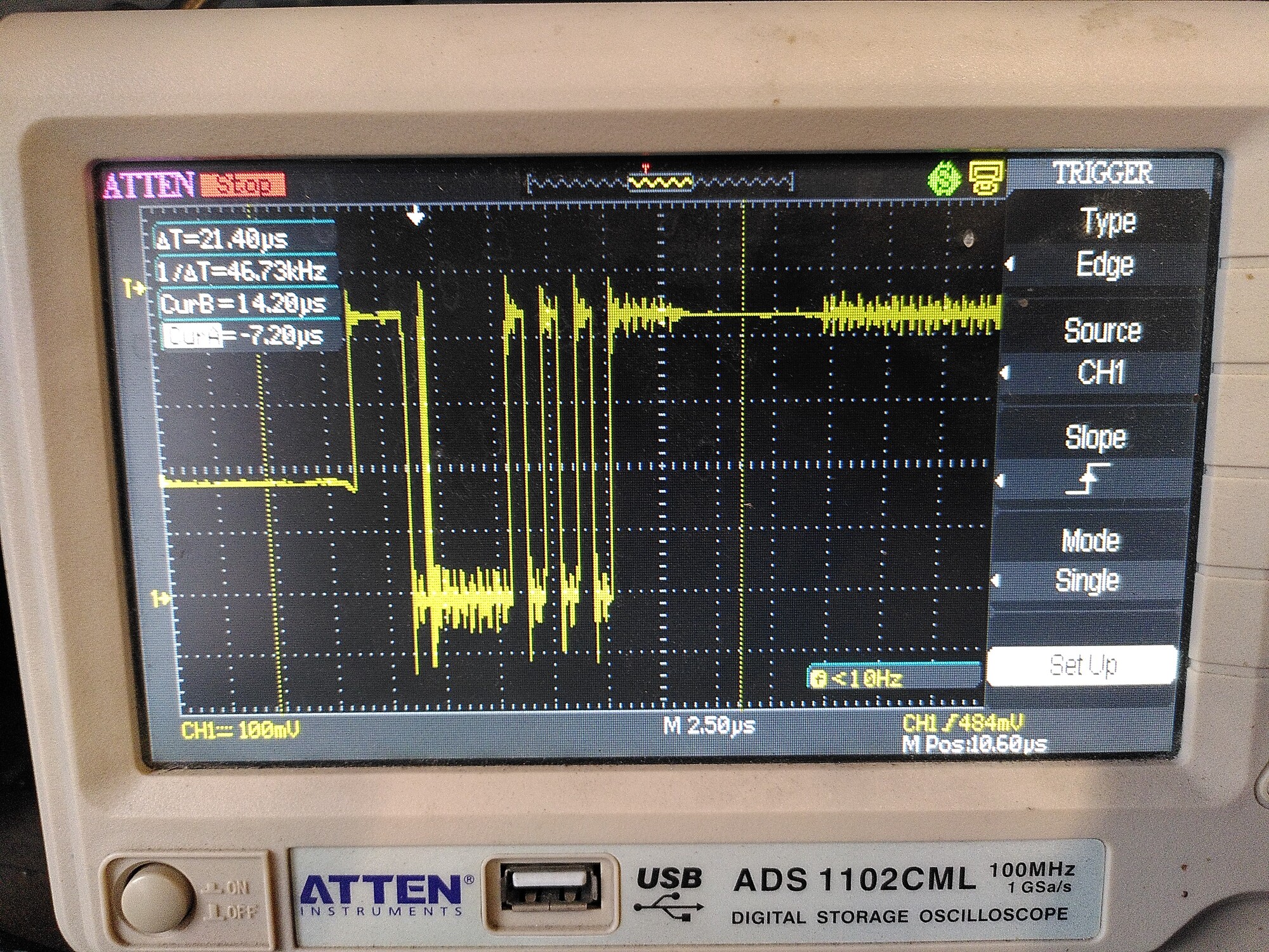
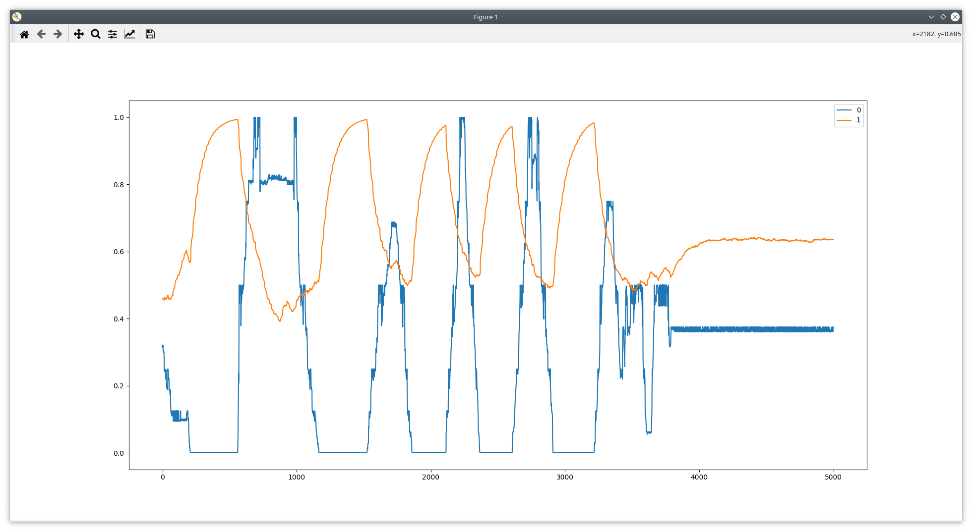
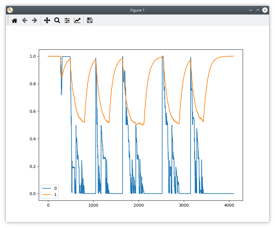
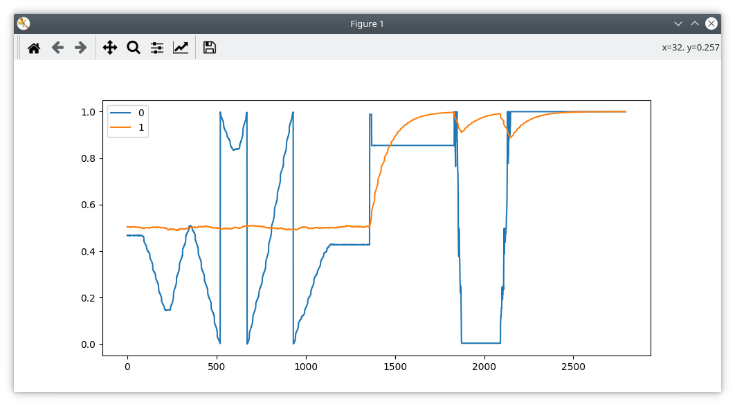
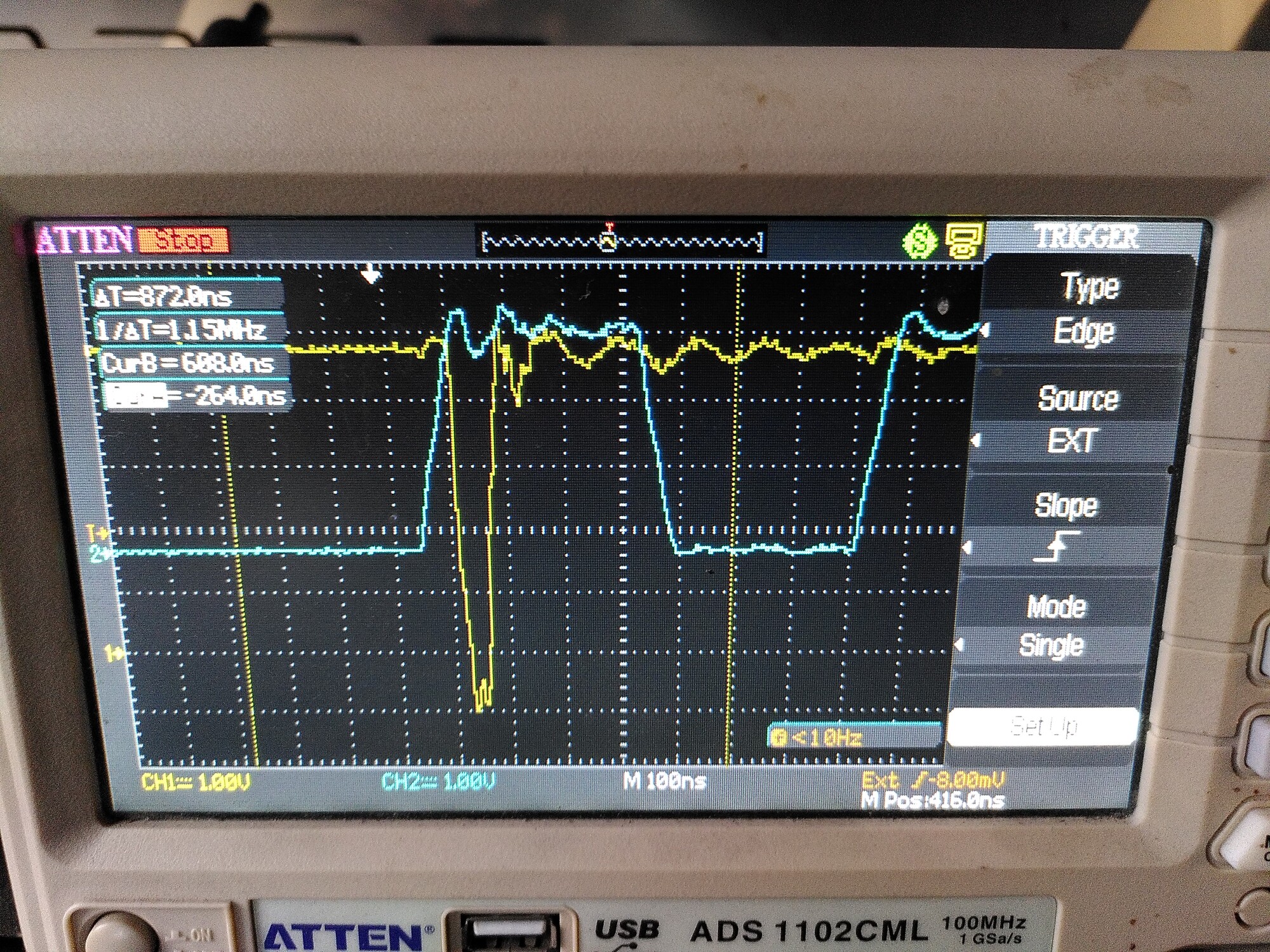
EDIT: Ok last post for a bit. I found some 20R resistors. I put one in the SCK wire.
Again, it is worse than having no resistor…
Graph to illustrate: I short out the resistor, move the motor by hand a few turns, then remove the short and repeat the same movement:

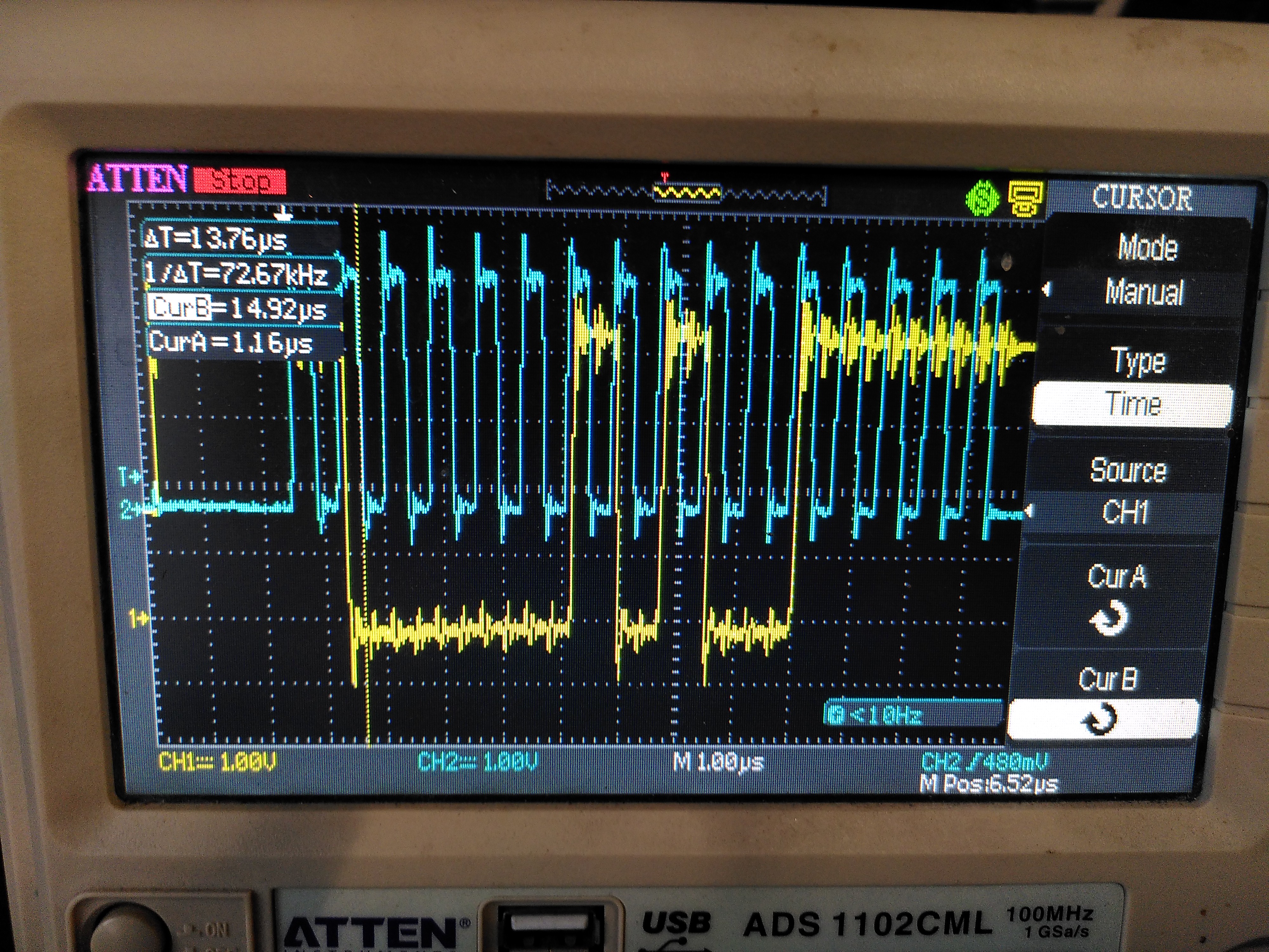
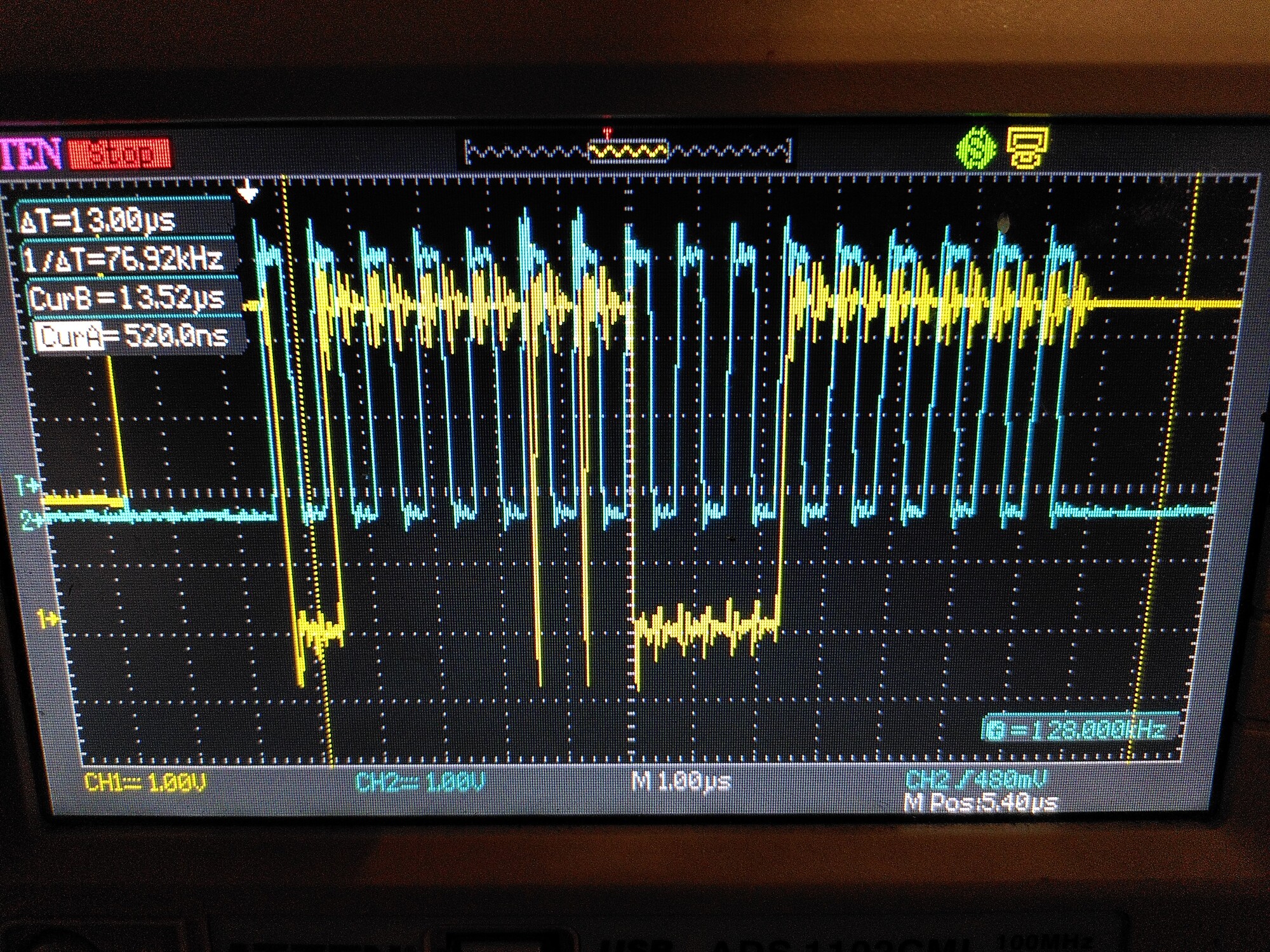
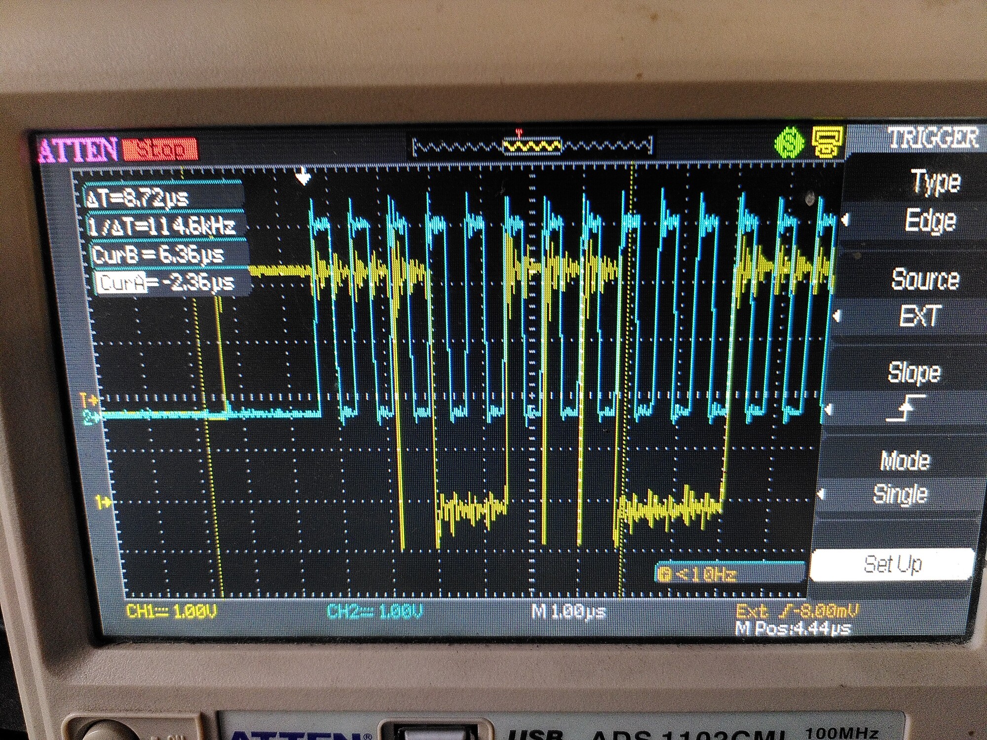
On the scope, I can see that the clock looks much cleaner, but there are those weird transients now present on MISO, like this:

(Blue is the clock. MISO should never change state at a higher rate than the clock)
It must be seeing some noise and interpreting it as a clock edge. But the probe is on the encoder side - there is hardly anything there to cause that.

Yeah, ignore the software thing, turned out to be fine how it was. I assume the encoder is in 3.3v mode?

Hmm no, I haven’t moved any resistors, and it is supplied with 5V. So it is in 5V mode.
But then again, it always was.

I suppose it’s possible that it was just on the edge of working before.