What values do you have for encoder.spi_error_rate and encoder.pos_in_cpr ?
I have personally been having a lot of problems with the AS5047P since early 2020 - I can’t tie it down to the ODrive hardware, software, or the chips themselves. It’s quite bizarre. The same wiring that used to work perfectly in the past doesn’t, even if I shorten it to a few cm.
The chips seem to be setting their internal error bit, with no explanation as to why - are we polling them too fast? No, I tried slowing that down to no effect. Are they damaged? No, I have ordered new chips and they behave the same.
In certain motor positions they seem to work - try putting both pos_in_cpr and spi_error_rate on the liveplotter and turning the motor very carefully by hand. Again I have no idea why they would do this.
I’ve all but given up on them, and will go for an alternative from MPS or CUI in future.
Is this likely to be a comms and/or noise issue then? I have followed the docs exactly, meaning the 3.3V is wired to the 3.3V, the GND is wired to the GND. The encoder is running entirely from the ODrive because I understood that would help avoid ground loops.
Should I have tied any other pins to any other values? Or done anything else to mitigate noise?
pos_in_cpr doesn’t exist, I assume “pos_cpr” is its replacement. The value of pos_cpr is fixed at 0.1249847412109375 no matter how much I hand-turn the motor.
What’s interesting is that spi_error_rate is also fixed. It stays identical, even to all those decimal places.
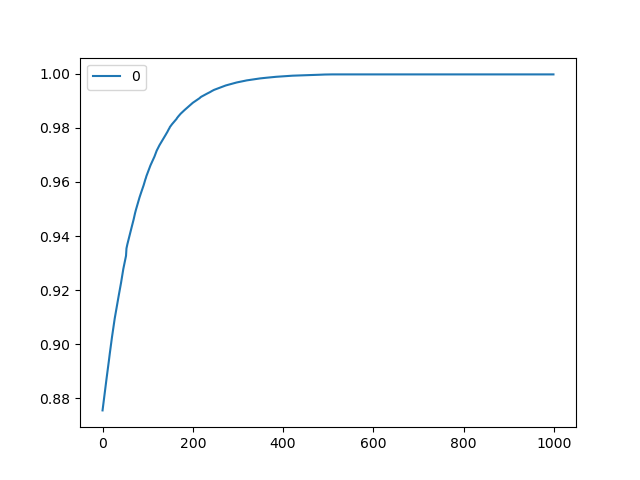
I tried turning the ODrive off and on again, and just measuring the spi_error_rate on the screen. It starts at around 0.918 and over the course of several seconds comes back to the exact same value 0.9997616410255432, from which it then never moves.
I tried it again, this time running liveplotter as soon as I turned it on. It gives a very clear graph:
Graph of spi_error_rate from switch on:
Does this phenomenon mean anything to anyone better acquainted with the ODrive firmware?
Thanks for pointing that out. I have moved R1 to R2 and left the wiring as it is.
As a result I now have one of two problems:
with JP1 on the left, I still see ENCODER_ERROR_ABS_SPI_COM_FAIL as soon as I turn on the ODrive (and persisting even after I clear the error a few times.) spi_error_rate floats around 0.5, and pos_cpr appears to fluctuate randomly even though I am not moving the motor at all.
with JP1 on the right (where I believe it’s supposed to be), I see no errors but all readings are exactly 0. That includes spi_error_rate, pos_cpr and everything else in odrv0.axis0.encoder. Despite claiming no errors, the ODrive does not respond when I do odrv0.axis0.requested_state = AXIS_STATE_FULL_CALIBRATION_SEQUENCE.
with JP1 removed entirely, I see the same symptoms as with JP1 on the left.
This makes me think JP1 should be on the right, but do I need to “turn it on” somehow?
I see ‘is_ready’ in .encoder (which is False) but nothing in .encoder.config that implies it will enable, activate or turn on the encoder.
The jumper jp1 is fairly pointless - it just connects the power input to either the 5v pin or the 3.3v pin on the header. You can just as easily desolder the jumper and connect either 5v or 3.3v directly to the middle pad.
(AS5047P-TS-EK-AB schematic - page 9)
However wetmelon is right, you need to move some resistors for it to work at 3.3v.
The garbage output and SPI_Error_Rate ~= 0.5 is exactly the behaviour I get, running on 5V.
It used to work fine on the end of a 2 metre cable, no issues whatsoever. Two motors both at 30A from a 50V supply.
Then after a few months it started to get SPI errors when the motor was running at a reasonable torque with 50V supply, and these errors went away if I lowered the supply voltage to 25V.
These days, it doesn’t work at all, with exactly the same hardware, firmware, etc. I have tried changing the firmware, the ODrive, the wiring, and the sensor board itself all to no avail. It’s weird.
My understanding is that the high error rate and nonsense readings are happening when I’m not actually powering the chip. JP1 is tying the centre pin to the 5V on the header, which is not connected.
When I place JP1 on the right, it’s tying the centre pin to 3.3V, which is connected to the ODrive.
That is when the errors vanish and I get a nice set of very neat and very useless zeroes when I print the .encoder object.
Right sorry - I misread your post.
If you’re getting readings with the chip unpowered, then the ODrive is clearly ‘trying’ to read it. There’s nothing else you should need to do to turn the chip ‘on’, other than to power it.
Nothing happens at all when you move the motor by hand? There are no positions in which you get a non-zero reading?
Also I assume you have saved config and rebooted?
Only other thing I could suggest is getting hold of an oscilloscope and checking what’s really going on with the SPI
I’m not sure whether I’m on the devel branch or not - that was actually one of the things I was initially asking about.
I don’t know where 0.5.1-dev comes from, and I’m not keen on overwriting it to then find I can’t get it back again. Without knowing where I stand on the firmware front, I’m not sure what I can rule it out as the cause of the problems.
I was hoping one of the devs would step in and clarify the situation, but I don’t know how closely they watch this forum.
And yes, I have saved and rebooted many, many times now.
So, I take it you have never compiled the firmware from source yourself?
0.5.1-dev /was/ a branch, it was closed when firmware 0.5.1 was released. You have some pre-release version of 0.5.1 but i’m not sure if its possible to tell exactly which. Is this the version that came shipped with the board?
If you auto-update now, (odrivetool dfu with no parameters) I think you will get the released 0.5.1 version.
It would also be worthwhile for you to clone the Git repo and check that you can build the current devel (even if you don’t flash it) this is the very latest but is changing all the time.
When I try running odrivetool dfu, it warns me that to proceed would be a step backwards since the version I have is more recent than the latest in the Git repo. So I haven’t gone ahead.
I would like to have a go at compiling the firmware for myself, since I (very optimistically) was thinking about playing around making some changes in there, once I’d got a handle on the more basic operation.
But I am very far away from that level of competence right now and it’s not going to help my current situation.
EDIT: I’ve cloned the ODrive repo and am looking through the commit logs now. The first reference to SPI I can see is from 31st December 2020, where they change something to do with a GPIO pin’s configuration. There is an earlier SPI-related fix on the 22nd December. Unfortunately I have no idea whether this info is relevant or not.
We made a mistake when we released 0.5.1, I built it from 1 commit beyond the tag and it got labeled “dev”. So it’s probably the 0.5.1 release code.
@jbombastor People have all sorts of problems with this dev board, I suggest doing a forum search because this problem has been solved a dozen times over
@Wetmelon How do you even do a forum search on here? I see no search bar anywhere. The “all categories” selector box gives you a search box that only seems to work with category headings. Previously on creating New Post it would try and find similar posts for me, but I’ve just tried it now and it either doesn’t come up or produces unhelpful results.
((EDIT: worked it out. Once it was dark outside, my monitor was bright enough for me to see the dim search icon in the top right corner. I can’t stop and look now but I will come back and see if it throws up any results that weren’t on Google.))
I had already read every post from here that Google would show me before posting. Most of what I found didn’t apply to the symptoms I’m getting, and most of the posts I read did not end in the problem being solved.
As a newcomer who doesn’t yet have the experience or know all the jargon, it’s quite possible I could have missed some important details because I didn’t know what to look for.
But I’m sure even I would have noticed if my problem had been solved a dozen times over.
If there is some resource I’ve missed, can anyone tell me where it is?
And, if this board is such a troublemaker, can the devs recommend one they know will actually work? Or are they all like this?
I assume from your response that the firmware on my ODrive is probably identical to the latest release, and so it’s safe to dfu update it. I’ll also assume that the ODrive can probably be trusted and the problem is with the encoder board.
A few more findings, posted here for completeness:
One chap posted on a different post that you need to tie the TEST pin to ground. (I don’t understand why you would, and there was no explanation given.) But I did that anyway, and now I get this result, which is subtly different from what I had before:
So we now have a hall_state, an interpolation and a phase. Although none of them do anything and pos_cpr still stays at 0 when I move the motor by hand.
However, now it actually lets me run odrv0.axis0.requested_state = AXIS_STATE_FULL_CALIBRATION_SEQUENCE
Unfortunately the result is an immediate ENCODER_ERROR_ABS_SPI_COM_FAIL. But still, it’s a result to report.
After that I tried to swap back to ABI mode, which never worked either. That didn’t work and gave me the error message ENCODER_ERROR_NO_RESPONSE when I ran AXIS_STATE_FULL_CALIBRATION_SEQUENCE.
I’m now going to wire the encoder board up to an arduino and see if I can see the ABI outputs changing onscreen when I move the motor by hand.
Well that’s answered one question. On wiring it up to the arduino, all three outputs (ABI) are high all the time, and the chip quickly gets hot to the touch. I guess it’s fucked somehow and I’ll have to buy another one.
I have no idea what would have caused that, but the first ODrive I bought did the same thing.
If it’s not throwing that error when IDLE but throws it when trying to calibrate, you have the classic SPI noise error, which is good because you’re making progress! Use short (< 6") SPI lines, use 50 ohm series resistors, shielded cable, or better yet - use shielded twisted pair over a differential bus (you have to add RS422 transceivers at both ends). Also, use the ferrite rings (available here) Personally, I don’t recommend SPI without differential, as it’s just too much trouble, unless you have EXTREMELY short wires.
I will be testing a differential encoder solution this coming week, so you may be able to get a known working solution directly from us shortly.
That’s news to me… I have seen a lot of threads about problems with the AS5047p but I fail to find one with a solution.
interesting re. the differential transievers! Although I am struggling to make it work even with wires <10cm - it’s infuriating because as I say, it used to work fine over several metres of cabling.
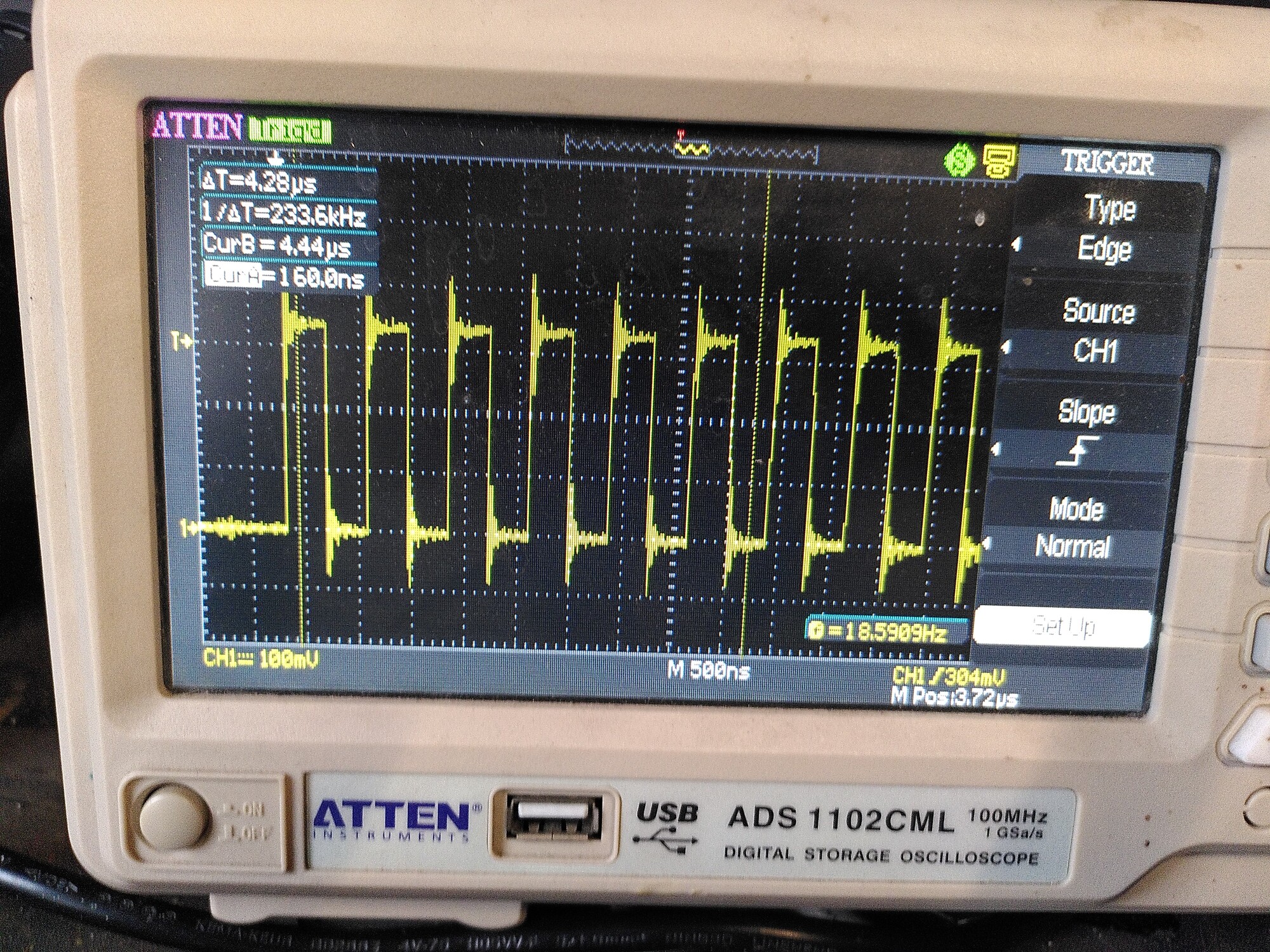
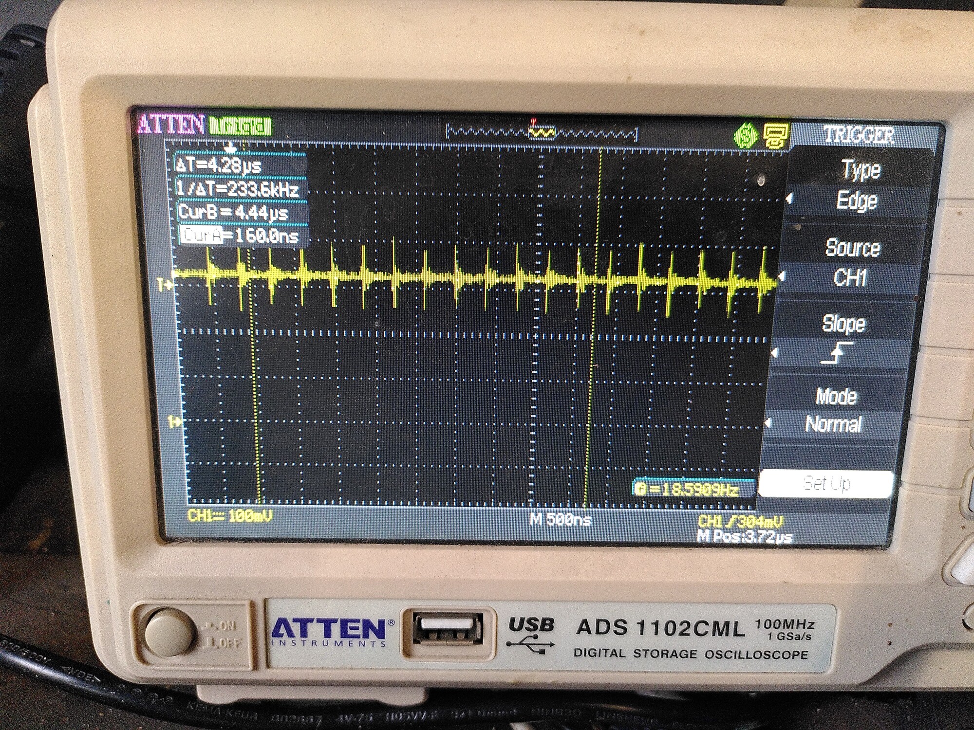
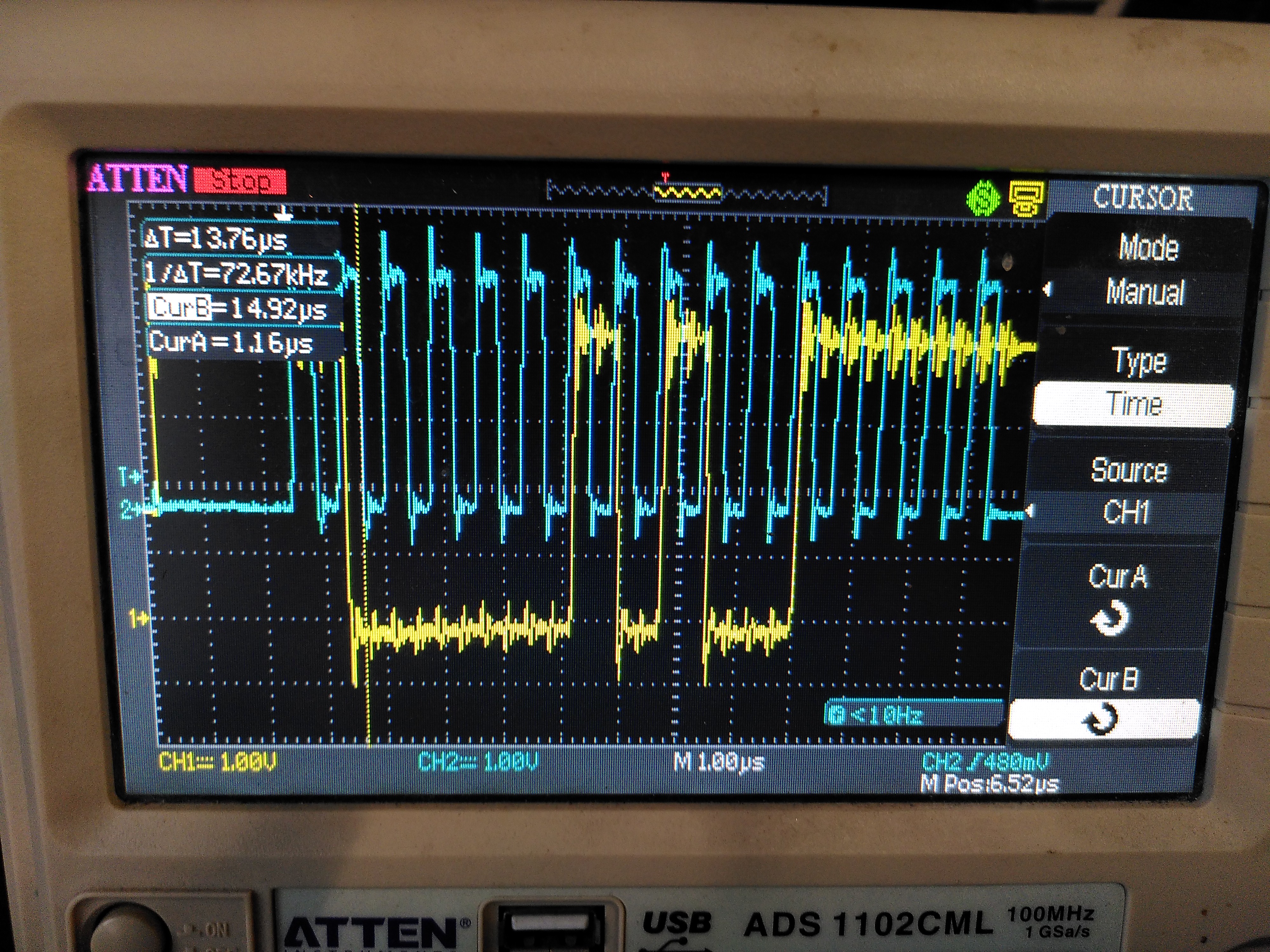
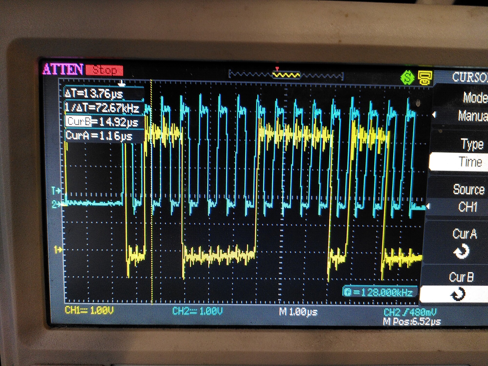
The first issue seems to be that there is a lot of ringing on the clock signal SCK - and it is coupling onto the MISO and MOSI lines. I guess that has to be wiring - I’ll try adding 50R series resistors.
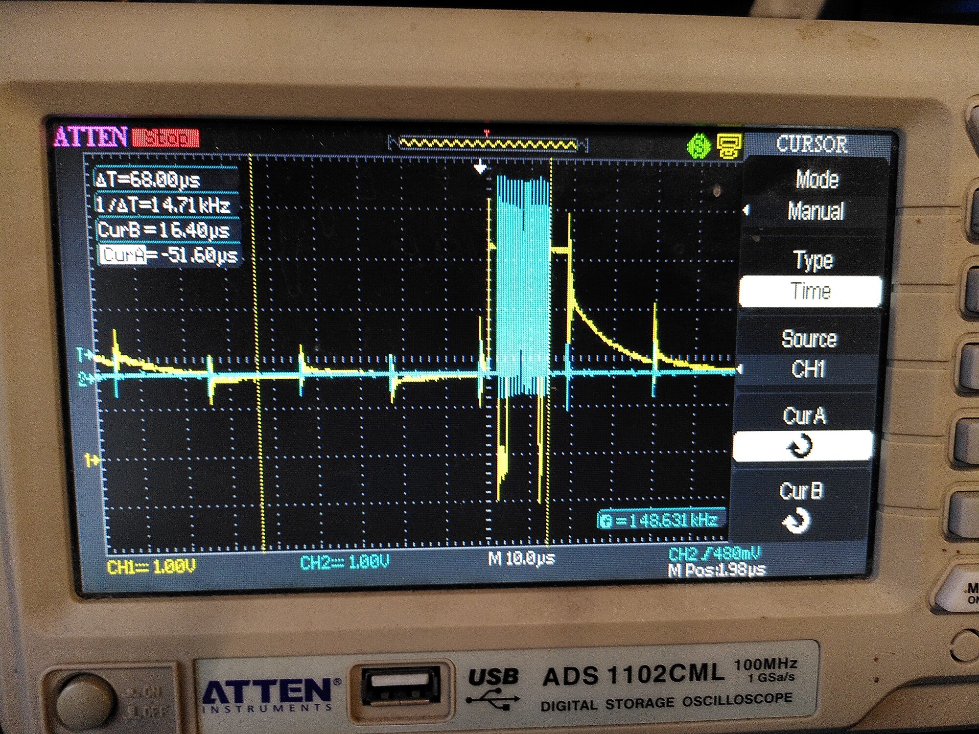
The second issue is that despite a ferrite on the motor wires, inverter switching noise is being coupled to all of the lines. The effect of that seems to be to throw the chip into some sort of ‘sulk’ state, where it sets its error bit high and keeps it there until a power cycle of the encoder itself.
This only happens when the motor is on, and it happens more quickly when the VBus voltage is higher. Above 20V it drops out in about 1 minute on average - above 30v it drops out in 10 seconds or so.
I can’t see how adding series resistors would help with this second issue.
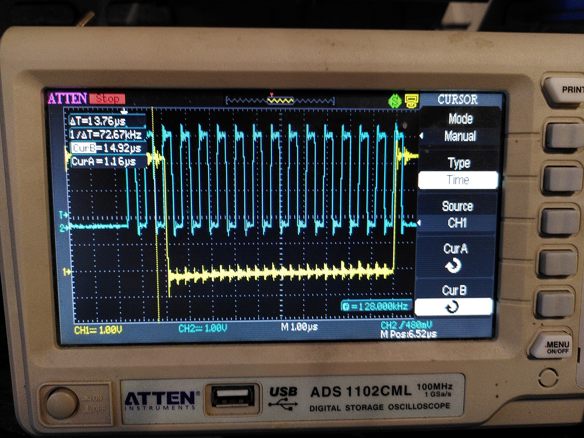
No error (note the bit at the cursor is low - that seems to be the error flag):
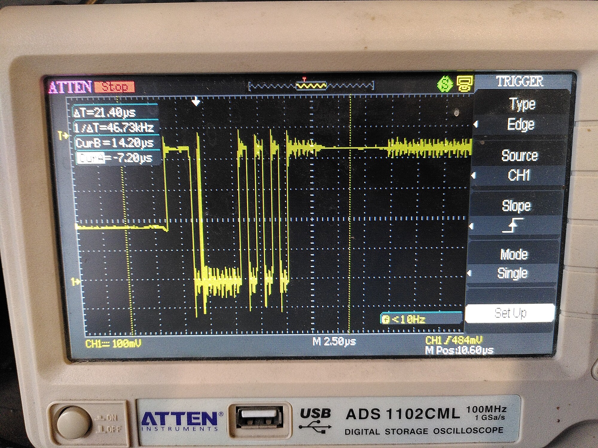
Now if you thought that was weird, here’s where it gets REALLY weird.
I have another AS5047p dev board on a different motor. This one has a 30cm cable with a connector (whereas the other one had a 3 metre cable with the same connector). Both cables are CAT5, with power/GND on a pair, MOSI/GND on a pair, MISO/GND on a pair, and SCK/CS on a pair.
I also have a 3 metre extension cable with the same connectors, also CAT 5. These cables used to work perfectly reliably, and are not damaged in any way as far as I can see.
If I plug my motor with the 30cm cable directly to the ODrive, immediately the error bit is high and stays there.
but if I move the motor a bit (it’s not on) then the encoder goes into a “super-sulk” state, and doesn’t just set the error flag, but returns a position value of 0 at all times until I reset the power.
Now here’s where it gets weirder: if I connect my 3 metre extension cable, it improves things: It still sets the error flag, but doesn’t enter the super-sulk state.
Maybe the extension cable is acting like those 50R resistors… I will try those next.
But again - this used to work 100% reliably! - wtf has changed??
EDIT: now it is not even setting the error flag, so long as it is on the long cable. So it’s behaving the same as the other motor - it works until I enable PWM.
But again, both of these motors worked fine all the way up to 55V, for weeks on end, about a year ago.