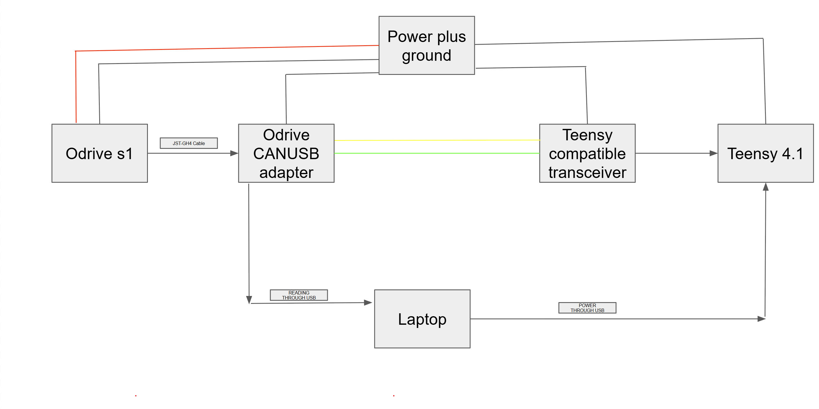
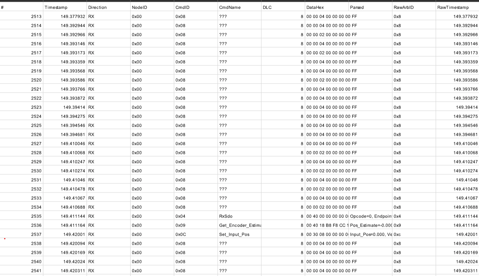
Hello, I have been using ODrive S1 for controlling 150KV motor using ODrive USB TO CAN adapter and a AI built CAN viewer tool on my laptop. It worked well. However I have now connected the system with a Teensy 4.1 and a compatible transceiver. When I read CAN Bus, I see 0x08 from same node ID 0 as ODrive (Teensy node id is set to 1) which I have never seen before and is not in the dbc too. I am attaching a CAN log and sketch of my setup. Has anyone ever faced this? Any suggestions are appreciated.
Thanks!
1 Like
Those aren’t from the ODrive – they’re CAN error frames from the USB-CAN adapter. It reports bus errors as ID 0x20000008 (error flag + protocol error); mask off the flag and you’re left with node 0, command 0x08. Byte 2 is the error type (0x04 stuff error, 0x02 form error) and the last byte is the adapter’s receive error counter, pegged at 255. So the bus has been erroring continuously since the Teensy joined – the ODrive itself never sends 0x08.
If the viewer’s on python-can, those messages will have is_error_frame == True. Pulling the Teensy’s transceiver off CANH/CANL should make them disappear entirely.
The Teensy’s own frames decode fine, so I’d look at the physical layer rather than the sketch. A few questions:
- Which transceiver, and what’s it powered from? The Teensy is 3.3V-only – a 5V transceiver like a TJA1050 can be marginal on a 3.3V TXD, and its 5V RXD isn’t safe for the Teensy either.
- How many 120R terminators are on the bus? Should be exactly two, at the ends. A lot of SN65HVD230 breakouts have one soldered on, and the adapter has its own switch.
- What bitrate and clock setting are you giving FlexCAN_T4?
1 Like
- I am using SN65HVD230 CAN Bus Transceiver for Teensy 4.1 and its getting powered from Teensy itself (3V pin)
- When I measure total CAN bus resistance it comes around 60 ohms, so I assumed resistance should be fine.
- Yes I think it was baudrate. It was set to 1000000 while my CAN was on 500K.
It doesnt have any question marks now. Thanks
1 Like
Could you send some pictures of the wiring? Or is everything working now?
1 Like
Yes the CAN works now, the issue is now that Teensy is not able to read the CAN message, so I think it’s more of teensy to transceiver issue than an ODRIVE.
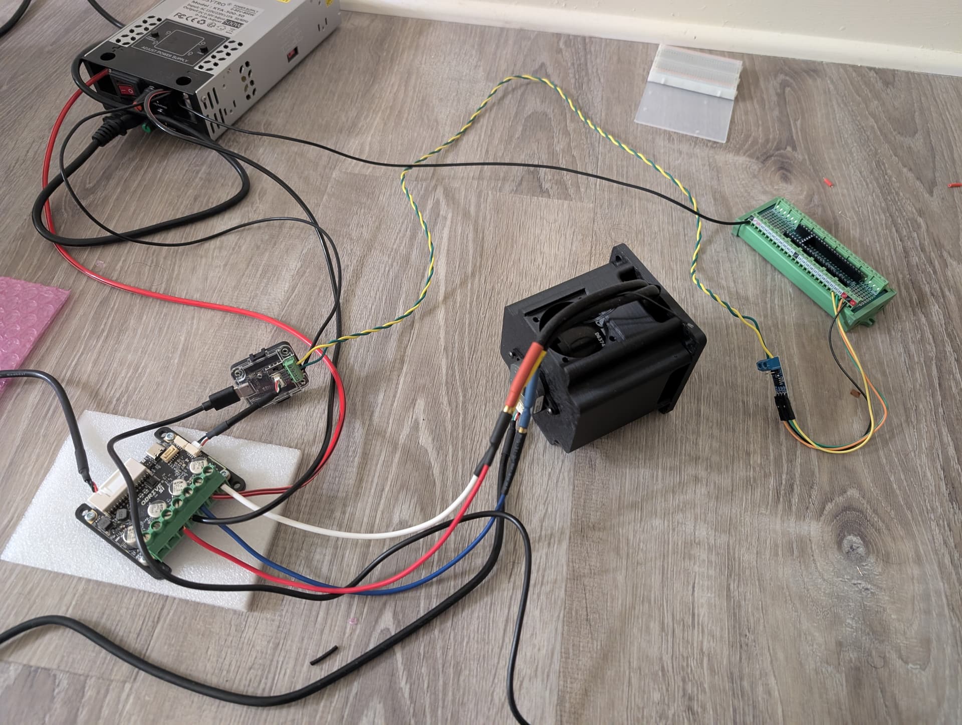
Here is my wiring although.
1 Like
Would you mind sharing your Teensy code?
1 Like
sure. The code below looks to set to toggle built in LED when it receives message (it also has code for external RGB LEDs, but not used). The code is used to blink the LED but since the rate is 10ms for the message looking for message from my CAN tool addressed to teensy on node ID 01, it should be fast enough to look like always ON LED once messages start
/*
- Teensy 4.1 — CAN message watcher + status reporter
- What it does:
-
- Listens on CAN1 for frames addressed to this Teensy (or broadcast).
-
- Each received message:
-
* blinks the built-in LED (pin 13) once -
* lights an external RGB LED in a color that depends on the command ID -
- Every STATUS_PERIOD_MS it sends a return CAN frame containing:
-
byte 0 = 1 if a message was received within IDLE_TIMEOUT_MS -
byte 0 = 0 if no message is being received - Return frame (what the ODrive CAN Viewer will show):
- CAN ID = (TEENSY_NODE_ID << 5) | STATUS_CMD_ID
-
= (1 << 5) | 0x1E = 0x3E (node 1, cmd 0x1E) - DLC = 1
- Data = 01 (reading) or 00 (idle)
- Wiring (same as before):
-
- Teensy 4.1 CAN1: TX = pin 22, RX = pin 23
-
- External CAN transceiver (SN65HVD230 / TJA1050) on pins 22/23, plus
-
120 ohm termination. -
- Built-in LED: pin 13 (single-color orange — used for the blink).
- RGB LED (for the “different colors” — the Teensy’s built-in LED is only
- one color, so this needs an external RGB LED):
-
- Common CATHODE RGB:
-
R -> pin 2, G -> pin 3, B -> pin 4 (each through ~220 ohm) -
common cathode -> GND -
set COMMON_ANODE = false -
- Common ANODE RGB:
-
R -> pin 2, G -> pin 3, B -> pin 4 (each through ~220 ohm) -
common anode -> 3.3V -
set COMMON_ANODE = true - Set RGB_ENABLE = 0 if you only want the built-in blink and no RGB LED.
- Library: FlexCAN_T4 (Tools → Manage Libraries → “FlexCAN_T4”)
- Board: Tools → Board → Teensy → Teensy 4.1
*/
#include <FlexCAN_T4.h>
// ---------------------------------------------------------------------------
// Configuration
// ---------------------------------------------------------------------------
#define TEENSY_NODE_ID 1 // CAN node ID this Teensy listens on / replies as
#define STATUS_CMD_ID 0x1E // custom command ID for the 1/0 status frame
#define CAN_BAUDRATE 500000 // must match the ODrive CAN Viewer bitrate (500 kbps)
#define LED_PIN 13 // built-in LED
#define RGB_ENABLE 1 // set to 0 if no external RGB LED
#define RED_PIN 2
#define GREEN_PIN 3
#define BLUE_PIN 4
#define COMMON_ANODE false // true = common-anode RGB (LOW turns a channel on)
#define IDLE_TIMEOUT_MS 500 // no message for this long => report 0
#define STATUS_PERIOD_MS 100 // how often to send the status frame
#define SERIAL_DEBUG 1 // print status changes to Serial (115200 baud)
FlexCAN_T4<CAN1, RX_SIZE_256, TX_SIZE_16> canBus;
// Shared with the CAN receive callback (runs in interrupt context).
volatile bool gotMessage = false;
volatile uint32_t lastRxTime = 0;
volatile uint8_t lastCmdId = 0;
// ---------------------------------------------------------------------------
// RGB helper
// ---------------------------------------------------------------------------
#if RGB_ENABLE
void setRgb(uint8_t r, uint8_t g, uint8_t b) {
if (COMMON_ANODE) {
analogWrite(RED_PIN, 255 - r);
analogWrite(GREEN_PIN, 255 - g);
analogWrite(BLUE_PIN, 255 - b);
} else {
analogWrite(RED_PIN, r);
analogWrite(GREEN_PIN, g);
analogWrite(BLUE_PIN, b);
}
}
void setColorForCmd(uint8_t cmdId) {
switch (cmdId) {
case 0x07: setRgb(255, 0, 0); break; // Set_Axis_State → red
case 0x0B: setRgb( 0, 255, 0); break; // Set_Controller_Mode → green
case 0x0D: setRgb( 0, 0, 255); break; // Set_Input_Vel → blue
case 0x0C: setRgb(255, 255, 0); break; // Set_Input_Pos → yellow
case 0x02: setRgb(255, 255, 255); break; // Estop → white
case 0x00: setRgb( 0, 255, 255); break; // Get_Version → cyan
case 0x01: setRgb(255, 0, 255); break; // Heartbeat → magenta
default: setRgb(255, 255, 255); break; // anything else → white
}
}
#endif
// ---------------------------------------------------------------------------
// CAN helpers
// ---------------------------------------------------------------------------
void sendStatus(uint8_t status) {
CAN_message_t msg;
msg.id = (TEENSY_NODE_ID << 5) | STATUS_CMD_ID;
msg.len = 1;
msg.buf[0] = status;
canBus.write(msg);
}
void onCanReceive(const CAN_message_t &msg) {
uint32_t nodeId = (msg.id >> 5) & 0x3F;
uint32_t cmdId = msg.id & 0x1F;
// Ignore frames addressed to other nodes (e.g. the ODrive’s own traffic).
// 0x3F is the broadcast node ID.
if (nodeId != TEENSY_NODE_ID && nodeId != 0x3F) {
return;
}
lastCmdId = (uint8_t)cmdId;
lastRxTime = millis();
gotMessage = true;
}
// ---------------------------------------------------------------------------
// Setup / loop
// ---------------------------------------------------------------------------
void setup() {
Serial.begin(115200);
delay(100);
pinMode(LED_PIN, OUTPUT);
digitalWrite(LED_PIN, LOW);
#if RGB_ENABLE
pinMode(RED_PIN, OUTPUT);
pinMode(GREEN_PIN, OUTPUT);
pinMode(BLUE_PIN, OUTPUT);
setRgb(0, 0, 0);
#endif
canBus.begin();
canBus.setBaudRate(CAN_BAUDRATE);
canBus.setMaxMB(16);
canBus.enableFIFO();
canBus.enableFIFOInterrupt();
canBus.onReceive(onCanReceive);
Serial.println(“Teensy CAN watcher ready.”);
}
void loop() {
static bool ledState = false;
// — Blink built-in LED once per message, and refresh the RGB color —
if (gotMessage) {
gotMessage = false;
ledState = !ledState;
digitalWrite(LED_PIN, ledState ? HIGH : LOW);
#if RGB_ENABLE
setColorForCmd(lastCmdId);
#endif
}
// — Idle detection —
bool active = (millis() - lastRxTime) < IDLE_TIMEOUT_MS;
#if RGB_ENABLE
static bool lastActive = false;
if (active != lastActive) {
lastActive = active;
if (!active) {
setRgb(0, 0, 0); // no traffic → RGB off
}
}
#endif
// — Send the 1/0 status frame periodically —
static uint32_t lastStatusSent = 0;
if (millis() - lastStatusSent >= STATUS_PERIOD_MS) {
lastStatusSent = millis();
sendStatus(active ? 1 : 0);
#if SERIAL_DEBUG
static uint8_t lastReported = 0xFF;
uint8_t now = active ? 1 : 0;
if (now != lastReported) {
lastReported = now;
Serial.print("Status: ");
Serial.println(now);
}
#endif
}
}
The code looks fine to me – the FlexCAN_T4 setup matches the library examples, and the node/command ID math is right.
In your wiring photo the Teensy socket on the DIN breakout looks empty – was it just pulled for the picture?
A few questions:
- Do the Teensy’s status frames (ID 0x3E) show up in your viewer? If they do, the Teensy’s TX, RX and bitrate are all working (it can’t get a frame onto the bus without reading it back), so the issue would be what’s being sent to it.
- What exactly is your tool sending to node 1? A viewer log of those frames would help.
Quick test: comment out the node ID check in onCanReceive and print msg.id to Serial. The ODrive’s heartbeat (ID 0x001) should show up 10x/second either way.
Yes sorry, teensy was just removed from DIN Breakout before the photo.
- No I dont see Teensy frames in my viewer, so I suspect either teensy is not receiving anyting to respond through transceiver.
- The tool is sending similar command of set input velocity to Teensy as a target (Node 1) instead of ODrive. It is just to test communication from CAN viewer to Teensy. I am adding the logs here. However there is still some time sync issue between ODrive clock and Teensy clock probably that you might see in logs, I dont think that should be a cause though.CAN Log
Gotcha. Agreed this might just be a transciever issue – worth checking the D/R lines between the Teensy and the transciever with a logic analyzer or oscilloscope.