Communication Issue with ODrive S1 Nodes via CAN Interface Beyond Certain Node IDs

Hello everyone!

I am experiencing a specific communication issue in my setup, which consists of multiple ODrive S1 controllers connected via a CAN bus, interfaced through an Arduino using an Waveshare SN65HVD230 CAN transceiver. My network includes several ODrive S1 units, each assigned unique CAN IDs and configured to share the same settings (heartbeat every 100ms, signals every 10ms), except for their node IDs. The CAN bus operates at a baud rate of 250000. Arduino is executing the SineWaveCAN example.

Problem Summary:

  • When addressing ODrive nodes individually through the Arduino (modifying the node ID in the Arduino code for each test), only nodes with the lowest 3 CAN IDs respond successfully to commands.
  • Specifically, the communication issue occurs when attempting to read the bus voltage and current from any node with a higher CAN ID (e.g., #4 and above). The Arduino code gets stuck at the point of sending this request, entering an infinite loop as the request fails.
  • This issue persists regardless of the physical order of the nodes on the CAN bus; nodes with higher IDs fail to communicate after the first few.
  • All nodes function correctly in smaller groups (3 or fewer), and the issue arises only when more nodes are added to the network, suggesting it’s not an individual node fault.
  • The CAN bus is properly terminated, and each node, including the end node, has been verified for correct configuration and termination. The power supply is stable and adequate for all nodes.

Troubleshooting Steps Taken:

  • Verified all ODrive S1 nodes are on the latest firmware (0.6.9-1).
  • Verified all ODrive S1 nodes work using a USB cable through the webgui’s Dashboard interface.
  • Confirmed CAN bus termination and grounding are correctly implemented.
  • Tested nodes in smaller group configurations (groups of 2 or 3) using Arduino+CAN, where they all work as expected.
  • Tested each node individually using Arduino+CAN, where each worked as expected
  • Increased delays and applied a retry system in the Arduino code, which hasn’t resolved the issue.
  • Conducted incremental node addition tests, isolating the issue to the handling of higher node IDs.
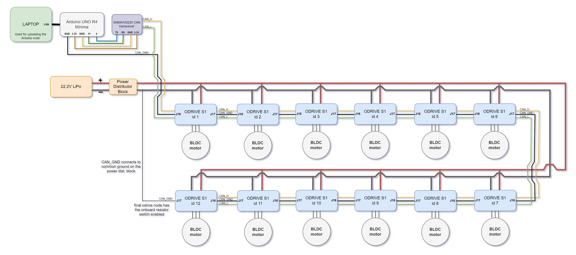
  • In the wiring diagram, its shown that all the nodes are connected from node id #1 being the first in the system, to #12 being last, even when this configuration is reversed, where #12 is first and #1 is last, only the 3 nodes with the lowest IDs seem to work. I have also randomized the configuration (ie, #4, #8, #1, #6, #12) and only the lowest 3 IDs (#4, #1, #6) worked in these configurations as well.
  • One thing I had noticed was that before upgrading the firmware on all ODrive S1s, groups up to 6 worked. After upgrading to firmware 0.6.9-1 only groups up to 3 works.

Seeking Support On:

  • Insights or solutions for handling communication with nodes that have higher CAN IDs in a network with multiple ODrive S1 units.
  • Any known issues or updates related to the ODrive firmware that might affect CAN communication in multi-node setups.
  • Recommendations for further diagnostic steps or adjustments to the CAN network configuration to achieve reliable communication with all nodes.

Here is what the wiring schematic looks like:

Here is my configuration setup looks like for one of the ODrive S1 nodes in the webgui:


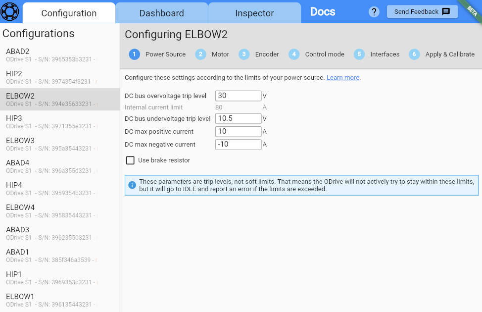
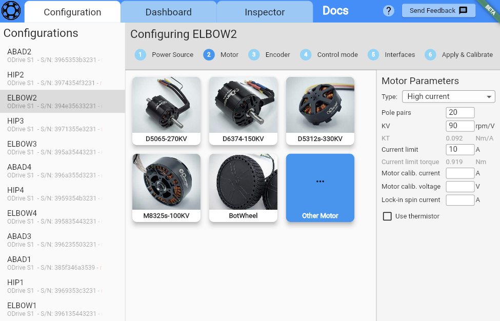
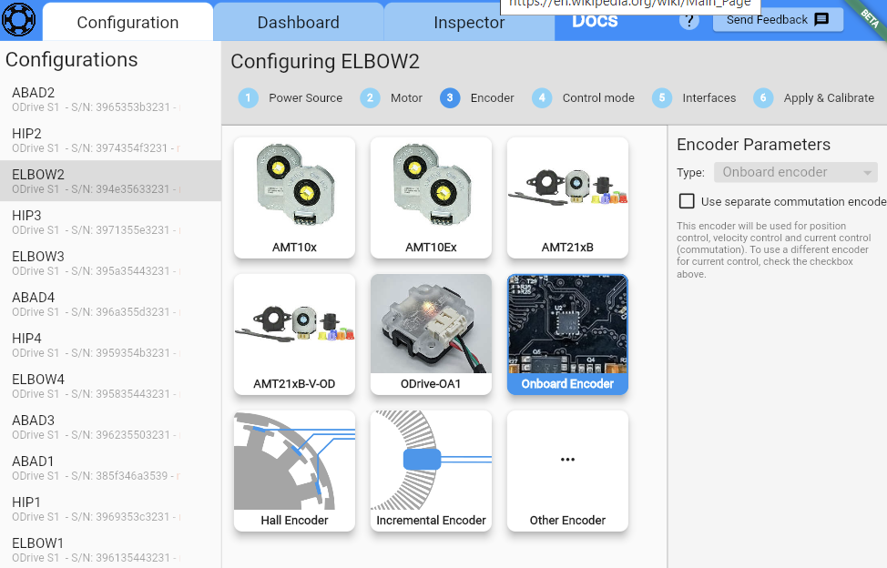
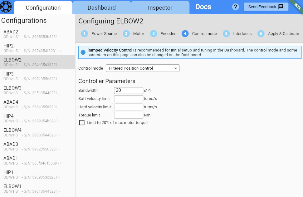
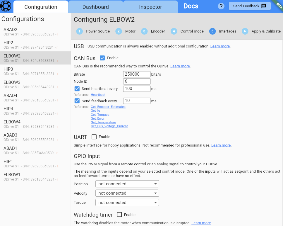
The only difference between all of the nodes is the Node ID, they are different for each node.

Here is the full Arduino code I am using (SineWaveCAN example):


#include <Arduino.h>
#include "ODriveCAN.h"

// Documentation for this example can be found here:
// https://docs.odriverobotics.com/v/latest/guides/arduino-can-guide.html


/* Configuration of example sketch -------------------------------------------*/

// CAN bus baudrate. Make sure this matches for every device on the bus
#define CAN_BAUDRATE 250000

// ODrive node_id for odrv0
#define ODRV0_NODE_ID 3

// Uncomment below the line that corresponds to your hardware.
// See also "Board-specific settings" to adapt the details for your hardware setup.

// #define IS_TEENSY_BUILTIN // Teensy boards with built-in CAN interface (e.g. Teensy 4.1). See below to select which interface to use.
#define IS_ARDUINO_BUILTIN // Arduino boards with built-in CAN interface (e.g. Arduino Uno R4 Minima)
// #define IS_MCP2515 // Any board with external MCP2515 based extension module. See below to configure the module.


/* Board-specific includes ---------------------------------------------------*/

#if defined(IS_TEENSY_BUILTIN) + defined(IS_ARDUINO_BUILTIN) + defined(IS_MCP2515) != 1
#warning "Select exactly one hardware option at the top of this file."

#if CAN_HOWMANY > 0 || CANFD_HOWMANY > 0
#define IS_ARDUINO_BUILTIN
#warning "guessing that this uses HardwareCAN"
#else
#error "cannot guess hardware version"
#endif

#endif

#ifdef IS_ARDUINO_BUILTIN
// See https://github.com/arduino/ArduinoCore-API/blob/master/api/HardwareCAN.h
// and https://github.com/arduino/ArduinoCore-renesas/tree/main/libraries/Arduino_CAN

#include <Arduino_CAN.h>
#include <ODriveHardwareCAN.hpp>
#endif // IS_ARDUINO_BUILTIN

#ifdef IS_MCP2515
// See https://github.com/sandeepmistry/arduino-CAN/
#include "MCP2515.h"
#include "ODriveMCPCAN.hpp"
#endif // IS_MCP2515

#ifdef IS_TEENSY_BUILTIN
// See https://github.com/tonton81/FlexCAN_T4
// clone https://github.com/tonton81/FlexCAN_T4.git into /src
#include <FlexCAN_T4.h>
#include "ODriveFlexCAN.hpp"
struct ODriveStatus; // hack to prevent teensy compile error
#endif // IS_TEENSY_BUILTIN


/* Board-specific settings ---------------------------------------------------*/


/* Teensy */

#ifdef IS_TEENSY_BUILTIN

FlexCAN_T4<CAN1, RX_SIZE_256, TX_SIZE_16> can_intf;

bool setupCan() {
  can_intf.begin();
  can_intf.setBaudRate(CAN_BAUDRATE);
  can_intf.setMaxMB(16);
  can_intf.enableFIFO();
  can_intf.enableFIFOInterrupt();
  can_intf.onReceive(onCanMessage);
  return true;
}

#endif // IS_TEENSY_BUILTIN


/* MCP2515-based extension modules -*/

#ifdef IS_MCP2515

MCP2515Class& can_intf = CAN;

// chip select pin used for the MCP2515
#define MCP2515_CS 10

// interrupt pin used for the MCP2515
// NOTE: not all Arduino pins are interruptable, check the documentation for your board!
#define MCP2515_INT 2

// freqeuncy of the crystal oscillator on the MCP2515 breakout board. 
// common values are: 16 MHz, 12 MHz, 8 MHz
#define MCP2515_CLK_HZ 8000000


static inline void receiveCallback(int packet_size) {
  if (packet_size > 8) {
    return; // not supported
  }
  CanMsg msg = {.id = (unsigned int)CAN.packetId(), .len = (uint8_t)packet_size};
  CAN.readBytes(msg.buffer, packet_size);
  onCanMessage(msg);
}

bool setupCan() {
  // configure and initialize the CAN bus interface
  CAN.setPins(MCP2515_CS, MCP2515_INT);
  CAN.setClockFrequency(MCP2515_CLK_HZ);
  if (!CAN.begin(CAN_BAUDRATE)) {
    return false;
  }

  CAN.onReceive(receiveCallback);
  return true;
}

#endif // IS_MCP2515


/* Arduinos with built-in CAN */

#ifdef IS_ARDUINO_BUILTIN

HardwareCAN& can_intf = CAN;

bool setupCan() {
  return can_intf.begin((CanBitRate)CAN_BAUDRATE);
}

#endif


/* Example sketch ------------------------------------------------------------*/

// Instantiate ODrive objects
ODriveCAN odrv0(wrap_can_intf(can_intf), ODRV0_NODE_ID); // Standard CAN message ID
ODriveCAN* odrives[] = {&odrv0}; // Make sure all ODriveCAN instances are accounted for here

struct ODriveUserData {
  Heartbeat_msg_t last_heartbeat;
  bool received_heartbeat = false;
  Get_Encoder_Estimates_msg_t last_feedback;
  bool received_feedback = false;
};

// Keep some application-specific user data for every ODrive.
ODriveUserData odrv0_user_data;

// Called every time a Heartbeat message arrives from the ODrive
void onHeartbeat(Heartbeat_msg_t& msg, void* user_data) {
  ODriveUserData* odrv_user_data = static_cast<ODriveUserData*>(user_data);
  odrv_user_data->last_heartbeat = msg;
  odrv_user_data->received_heartbeat = true;
}

// Called every time a feedback message arrives from the ODrive
void onFeedback(Get_Encoder_Estimates_msg_t& msg, void* user_data) {
  ODriveUserData* odrv_user_data = static_cast<ODriveUserData*>(user_data);
  odrv_user_data->last_feedback = msg;
  odrv_user_data->received_feedback = true;
}

// Called for every message that arrives on the CAN bus
void onCanMessage(const CanMsg& msg) {
  for (auto odrive: odrives) {
    onReceive(msg, *odrive);
  }
}

void setup() {
  Serial.begin(115200);

  // Wait for up to 3 seconds for the serial port to be opened on the PC side.
  // If no PC connects, continue anyway.
  for (int i = 0; i < 30 && !Serial; ++i) {
    delay(100);
  }
  delay(200);


  Serial.println("Starting ODriveCAN demo");

  // Register callbacks for the heartbeat and encoder feedback messages
  odrv0.onFeedback(onFeedback, &odrv0_user_data);
  odrv0.onStatus(onHeartbeat, &odrv0_user_data);

  // Configure and initialize the CAN bus interface. This function depends on
  // your hardware and the CAN stack that you're using.
  if (!setupCan()) {
    Serial.println("CAN failed to initialize: reset required");
    while (true); // spin indefinitely
  }

  Serial.println("Waiting for ODrive...");
  while (!odrv0_user_data.received_heartbeat) {
    pumpEvents(can_intf);
    delay(90);
  }
  delay(100);
  Serial.println("found ODrive");

  // request bus voltage and current (1sec timeout)
  Serial.println("attempting to read bus voltage and current");
  Get_Bus_Voltage_Current_msg_t vbus;
  int retries = 0;
  while (!odrv0.request(vbus, 1) && retries < 3) {
    Serial.println("Request failed, retrying...");
    delay(200); // Increase delay before retry
    retries++;
  }
  if (retries >= 3) {
    Serial.println("vbus request failed after retries!");
    while (true); // Consider a recovery strategy other than infinite loop
}

  Serial.print("DC voltage [V]: ");
  Serial.println(vbus.Bus_Voltage);
  Serial.print("DC current [A]: ");
  Serial.println(vbus.Bus_Current);

  Serial.println("Enabling closed loop control...");
  while (odrv0_user_data.last_heartbeat.Axis_State != ODriveAxisState::AXIS_STATE_CLOSED_LOOP_CONTROL) {
    odrv0.clearErrors();
    delay(1);
    odrv0.setState(ODriveAxisState::AXIS_STATE_CLOSED_LOOP_CONTROL);

    // Pump events for 150ms. This delay is needed for two reasons;
    // 1. If there is an error condition, such as missing DC power, the ODrive might
    //    briefly attempt to enter CLOSED_LOOP_CONTROL state, so we can't rely
    //    on the first heartbeat response, so we want to receive at least two
    //    heartbeats (100ms default interval).
    // 2. If the bus is congested, the setState command won't get through
    //    immediately but can be delayed.
    for (int i = 0; i < 15; ++i) {
      delay(10);
      pumpEvents(can_intf);
    }
  }

  Serial.println("ODrive running!");
}

void loop() {
  pumpEvents(can_intf); // This is required on some platforms to handle incoming feedback CAN messages

  float SINE_PERIOD = 2.0f; // Period of the position command sine wave in seconds

  float t = 0.001 * millis();
  
  float phase = t * (TWO_PI / SINE_PERIOD);

  odrv0.setPosition(
    sin(phase) * 0.2, // position
    cos(phase) * (TWO_PI / SINE_PERIOD) * 0.2 // velocity feedforward (optional)
  );

  // print position and velocity for Serial Plotter
  if (odrv0_user_data.received_feedback) {
    Get_Encoder_Estimates_msg_t feedback = odrv0_user_data.last_feedback;
    odrv0_user_data.received_feedback = false;
    Serial.print("odrv0-pos:");
    Serial.print(feedback.Pos_Estimate);
    Serial.print(",");
    Serial.print("odrv0-vel:");
    Serial.println(feedback.Vel_Estimate);
  }
}

Hi there,

Thank you so much for the detailed writeup, that really makes things easy!

My initial thought is that this seems like a clear case of the bus being overloaded - 12x S1s each sending 10Hz heartbeats and 100Hz for all other periodic messages is ~8.5 KB/s per ODrive. 250,000 baud is only about 31250 KB/s of bandwidth, and CAN busses start to get unreliable over about 50% bus load.

Due to how CAN arbitration works, lower node IDs get priority - so I’m definitely not surprised that it’s just the lowest three nodes that are able to communicate.

My recommendation would be to bump the CAN bus baudrate up to the max supported (1Mbps) and to reduce the frequency of lower priority messages - e.g. Get_Temperature probably only needs to be 1-10Hz, most applications don’t require per-ODrive bus voltage/current measurements, usually only one of Iq or torque is needed, etc. That should let you comfortably run your 12x S1s with 100Hz feedback where it matters.

1 Like

Problem solved, thank you so much Solomon as always!

This was exactly my problem. It also explains why in my initial tests I was able to move 6 motors, and after the firmware update, it was reduced to 3. It was because I had also changed the settings so the feedback was sent every 10 ms, whereas prior to the firmware upgrade it was set to be sent every 100ms.

I kept all settings the same as shown in my pictures in this thread, except the bitrate is now set to 1000000 instead of 250000.

Thanks a ton!
-Ali

1 Like

Great to hear that worked! Yes, that all makes sense!

Would definitely recommend keeping bus load under 50% in general – at 8.5KB/s per ODrive * 12 = 102 KB/s, and 1Mbaud == 125KB/s, you’re at around 81.6% utilization, which may cause dropped messages and conflicts. I think reducing the baudrate of temperature, error, bus voltage/current, and either torques or Iq would probably help - you only need to reduce down to ~6KB/s per ODrive (assume each message is ~14 bytes).

1 Like

Sounds great! In my current system, I think it should safe for me to adjust the intervals for all feedback messages instead of just the ones you have mentioned (lazier route through the webgui).

…and using the formula you have provided for the old setup (Heartbeat every 100ms & feedback every 10ms):

14 bytes x 6 messages (84 bytes) @ 10ms = 8.2 kB/s
+1 heartbeat message @ 100ms = 0.137 kB/s
= 8.337 kB/s per ODrive, x 12 = ~100 kB/s

And the updated (Heartbeat every 100ms & feedback every 20ms):

14 bytes x 6 messages (84 bytes) @ 20ms = 4.1 kB/s
+1 heartbeat message @ 100ms = 0.137 kB/s
= 4.2 kB/s per ODrive, x 12 = ~50 kB/s

1Mbaud == 125KB/s, which lands me to around 40% load for the entire system.

Thank you so much for all this info, what a great learning experience!

That all looks about right! Glad I could help :slight_smile:

Hello Solomon,
Thank you so much for all the help on this thread,

I have a couple of questions if you don’t mind,

i am controlling 6 ODrives through Teesny4.1 using UART communication, i couldn’t achieve high communication speeds (max i could get was around 60 HZ), i am considering moving to CAN for a variety of reasons but mainly speed boost,

My first question is, do you think a 300-500 HZ communication speed is achievable on 6 ODrives S1 using CAN communication? if yes, directions please!

Second question would help the first one,
How do i decrease the baudrate for each individual command (temperature, error, bus voltage/current, and torques or Iq)?

One last question because i lied about having 2 questions,
it mentions in the documentation that the S1 and PRO will support CAN-FD soon at 8mbps, any idea when this is happening?

Thank you,
Ahmet

Hi there,

What’s your baudrate? Are you using software serial or hardware serial? You should be able to communicate higher than 60Hz – this may be an issue with your application code. If you use a higher baudrate and properly use DMA and interrupts, you should be able to reach much higher communications speeds than 60Hz.

CAN communication speed is going to be dependent on total bus load. Assuming a bus speed of 1Mbps, each cyclic message takes about 14 bytes. So if I have six ODrives, each sending the heartbeat at 10Hz, and two cyclic messages at 500Hz each, that’s 6 * (10*14Byte (for heartbeat) + 2*500*14Byte (for other cyclic messages) = 84840 Byte/s, which is 678720 bit/s. You generally want to keep bus load below 50%, so this may be a bit too high. However, the Teensy has three CAN busses, so you could have two ODrives per CAN bus and likely not have an issue with communications speed.

What do you mean “decrease the baudrate” - do you mean change how often cyclic messages are sent? You just change the *rate_ms properties here: ODrive API Reference — ODrive Documentation 0.6.9 documentation

Ultimately, your performance is going to be heavily affected by the specific data you need from the ODrive as well as the efficiency of your application code.

CAN-FD is a bit deceptive - the negotiation takes place at a lower speed (1Mbps max), so it’s not a straight 8x speed increase – it would only give about 3x more bandwidth if implemented as-is – but that’s still a lot! Proper CAN-FD utilization will require a restructuring of how the ODrives handle cyclic messages, batching together multiple messages for optimal utilization of the high-speed CAN-FD data frame.

Thank you Solomon,
The baudrate i am using is 625000, and i am using hardware serial to establish odrive serial object,

HardwareSerial& odrive_serial1 = Serial1;

The code establishes UDP communication through ethernet, the 60HZ i am talking about includes sending the udp package to target pc,
I am sending only positions values for now, but i will need to extend that to position and current, and also command motor with desired torque, so, that’s quite limiting,

Any directions regarding DMA and interrupts?

A silly question regarding decreasing cyclic messages rate, does it matter to decrease the rate for messages i am not requesting? motor temperature or voltage for example,

Lastly regarding using multiple CAN busses on Teensy4.1, i guess i will need a tranceiver for each bus, and therefore, i can’t daisy chain all 6 odrives together, but rather two at a time?

Thank you,

Ah - yeah, I’m not surprised that a bunch of application code is hurting your loop speed. Maybe using something like FreeRTOS would help? That way you don’t have to wait on your ethernet packets for the ODrive control, etc etc.

DMA/interrupts are more advanced embedded programming, would you be willing to share your application code?

Yes - you can definitely decrease the rate of cyclic messages you’re not using to save bus load! Would absolutely recommend that.

And yes, you’d need to have two at a time, with three transceivers. That being said, what exact cyclic messages do you need and at what rate? I’m wondering if your 300-500Hz is achievable with a single CAN bus. Knowing more details about how exactly you envision the communications flow to be would help me figure this out!

Also - I totally screwed up my math with the CAN-FD thing – it would be a 3x overall communications speed increase, not 1/3x – my apologies there! We definitely hope to have CAN-FD support soon, but there are some other things we’re working to get to first, like better CAN support in the GUI.

Thank you Solomon,
I definitely don’t mind sharing the code, as a matter of fact , i appreciate your time going through it,
You will notice some redundant lines of script that could be avoided with for loops, this is a test script and not final iteration,

// Script to read from and command to all 6 motors in Real-Time followed
// by sending to host-pc throuh UDP Packets
#include <iostream>
#include <stdlib.h>
#include <string.h>
#include <stdio.h>
#include <SPI.h>

// Includes needed for Ethernet
#include <Ethernet.h>
#include <EthernetUdp.h>

// Includes needed for motor controller
#include <ODriveArduino.h>

// The baudrate must match the baudrate configured on the ODrive.
// Note that the default clock speed for Teensy 4.1 is 2Mhz but can reach 600MHz without cooling.
// Therefore max theoretical baudrate without cooling on Teensy side is 37500000
// Min clock period for SPI to read encoder is 100 ns which implies max baudrate to be 625000
// Therefore max theoretical baudrate is 625000
float baudrate = 625000; //max theoretical is 625000

// Visit Pjrc website for serial pin inputs // RX (ODrive TX), TX (ODrive RX)
HardwareSerial& odrive_serial1 = Serial1;
HardwareSerial& odrive_serial2 = Serial2;
HardwareSerial& odrive_serial3 = Serial3;
HardwareSerial& odrive_serial4 = Serial5;
HardwareSerial& odrive_serial5 = Serial7;
HardwareSerial& odrive_serial6 = Serial8;

// Initialize Odrive Object
ODriveArduino odrive1(odrive_serial1);
ODriveArduino odrive2(odrive_serial2);
ODriveArduino odrive3(odrive_serial3);
ODriveArduino odrive4(odrive_serial4);
ODriveArduino odrive5(odrive_serial5);
ODriveArduino odrive6(odrive_serial6);

// ******************************//
// Homing Parameters
//*******************************//
//float Motor_home[6] = {1.5708, 1.5708, 1.5708, 0.7854, 0.7854, 1.5708}; // [Rad] - Home Positions at Joint Level - TEMP
float Motor_home[6] = {1.0472, 1.3962, 1.5708, 1.1519, 1.0035, 1.5708}; // [Rad] - for Right Arm

// Motors 1, 2, 3 (upper 5-bar), 4,5,6 (lower 5-bar)
float Motor_offset[6] = {3.14159, 3.14159, 1.5708, 1.5708, 1.5708, 1.5708}; // [Rad] - offset to match kinematic model in MATLAB
float Capstan_Ratio = 20.0 / 80.0; // Gear Ratio For motors 1,2,4 and 5
float Belt_Ratio = 16.43 / 68.0; // Gear Ratio (MISUMI Belts) For moto 3 and 6
float Encoder_Ratio = 6.2832; // [rad/turn]
float Encoder_Home = 0.5; // [Turns] For all 6 motors
double q_enc[6]; // [Turns] - Current Reading at Motor Level
double q_curr[6]; // [Rad] - Current Reading at Joint Level (Output Level)

double Motor_Torque[6];
int Kv = 330.0; // [rpm/V] Specified to D5312S Motor
double Torque_Const = 8.27 / Kv; //[Nm/A]

// ******************************//
// Flags //
// Flag to Enable Closed Loop Mode for all motors. If 0 disabled.
int enable_CL_mode = 0;

// ******************************//
// Ethernet vars
//*******************************//
byte mac[] = {0xDE, 0xAD, 0xBE, 0xEF, 0xFE, 0xFE};
IPAddress ip(192, 168, 1, 135); // local ip - Teensy 192.168.1.134 for left arm
IPAddress sendIP(192, 168, 1, 101); // remote ip - Host PC
unsigned int localPort = 2003;      // local port to listen on
unsigned int sendPort = 2002;      // remote port to send to // 2001 for left arm

const int num_values_in_data_array = 6;
const int num_bytes_in_message = num_values_in_data_array * 4; // we are sending doubles (4 bytes per float)

union {
  float values[num_values_in_data_array];
  char data_buffer[num_bytes_in_message];
} send_data;

union {
  float values[num_values_in_data_array];
  char data_buffer[num_bytes_in_message];
} recv_data;

// Declare the UDP object
EthernetUDP Udp;

// ************* Void Setup ************** //
void setup() {
  odrive_serial1.begin(baudrate);
  odrive_serial2.begin(baudrate);
  odrive_serial3.begin(baudrate);
  odrive_serial4.begin(baudrate);
  odrive_serial5.begin(baudrate);
  odrive_serial6.begin(baudrate);

  Serial.begin(625000);

  delay(10);

  // Initialize Odrives' Axis State
  Serial.println("Waiting for ODrives...");
  while (odrive1.getState() == AXIS_STATE_UNDEFINED || odrive2.getState() == AXIS_STATE_UNDEFINED || odrive3.getState() == AXIS_STATE_UNDEFINED
         || odrive4.getState() == AXIS_STATE_UNDEFINED || odrive5.getState() == AXIS_STATE_UNDEFINED || odrive6.getState() == AXIS_STATE_UNDEFINED) {

    odrive1.clearErrors();
    if (odrive1.getState() != AXIS_STATE_UNDEFINED) {
      Serial.println("ODRIVE1 IS ACTIVE");
    };

    odrive2.clearErrors();
    if (odrive2.getState() != AXIS_STATE_UNDEFINED) {
      Serial.println("ODRIVE2 IS ACTIVE");
    };

    odrive3.clearErrors();
    if (odrive3.getState() != AXIS_STATE_UNDEFINED) {
      Serial.println("ODRIVE3 IS ACTIVE");
    };

    odrive4.clearErrors();
    if (odrive4.getState() != AXIS_STATE_UNDEFINED) {
      Serial.println("ODRIVE4 IS ACTIVE");
    };

    odrive5.clearErrors();
    if (odrive5.getState() != AXIS_STATE_UNDEFINED) {
      Serial.println("ODRIVE5 IS ACTIVE");
    };

    odrive6.clearErrors();
    if (odrive6.getState() != AXIS_STATE_UNDEFINED) {
      Serial.println("ODRIVE6 IS ACTIVE");
    };

    delay(100);
  }

  // Check Step - Read DC Voltage for a motor and print it to Serial
  //    Serial.print("DC voltage motor 1: ");

  if (enable_CL_mode == 1) {  // Enable Closed Loop Control
    Serial.println("Enabling closed loop control...");
    while (odrive1.getState() != AXIS_STATE_CLOSED_LOOP_CONTROL) {
      odrive1.clearErrors();
      odrive1.setState(AXIS_STATE_CLOSED_LOOP_CONTROL); // AXIS_STATE_CLOSED_LOOP_CONTROL
      delay(10);
    }
    while (odrive2.getState() != AXIS_STATE_CLOSED_LOOP_CONTROL) {
      odrive2.clearErrors();
      odrive2.setState(AXIS_STATE_CLOSED_LOOP_CONTROL);
      delay(10);
    }
    while (odrive3.getState() != AXIS_STATE_CLOSED_LOOP_CONTROL) {
      odrive3.clearErrors();
      odrive3.setState(AXIS_STATE_CLOSED_LOOP_CONTROL);
      delay(10);
    }
    while (odrive4.getState() != AXIS_STATE_CLOSED_LOOP_CONTROL) {
      odrive4.clearErrors();
      odrive4.setState(AXIS_STATE_CLOSED_LOOP_CONTROL);
      delay(10);
    }
    while (odrive5.getState() != AXIS_STATE_CLOSED_LOOP_CONTROL) {
      odrive5.clearErrors();
      odrive5.setState(AXIS_STATE_CLOSED_LOOP_CONTROL);
      delay(10);
    }
    while (odrive6.getState() != AXIS_STATE_CLOSED_LOOP_CONTROL) {
      odrive6.clearErrors();
      odrive6.setState(AXIS_STATE_CLOSED_LOOP_CONTROL);
      delay(10);
    }
  }

  Serial.println("ODrives are running!");

  // setup for Ethernet UDP
  Ethernet.begin(mac, ip);
  Udp.begin(localPort);
  delay(100);

  Serial.println("UDP port established");

}

void loop() {
  //  timer.start();
  //
  //Recieve via UDP
  int packetSize = Udp.parsePacket();
  //  Serial.println("\n Bytes received:");
  //  Serial.println(packetSize);
  Udp.read(recv_data.data_buffer, sizeof(recv_data.data_buffer));
  if (packetSize) {
    Serial.println("\n Bytes received:");
    Serial.println(packetSize);
    Serial.println("Data recieved:");
    for (int i = 0; i < (packetSize / 4); i++) {
      Serial.print(recv_data.values[i]);
      Serial.print(" ");
    }
  }

  Serial.println("Motor Torques:");
  double Odrive1_Current = odrive1.getParameterAsFloat("axis0.motor.foc.Iq_setpoint");
  double Odrive1_Torque = Odrive1_Current * Torque_Const;
  Motor_Torque[0] = {Odrive1_Torque};
  Serial.print("Odrive1:");
  Serial.println(Odrive1_Torque, 3);
  Serial.println();

  double Odrive2_Current = odrive2.getParameterAsFloat("axis0.motor.foc.Iq_setpoint");
  double Odrive2_Torque = Odrive2_Current * Torque_Const;
  Motor_Torque[1] = {Odrive2_Torque};
  Serial.print("Odrive2:");
  Serial.println(Odrive2_Torque, 3);
  Serial.println();

  double Odrive3_Current = odrive3.getParameterAsFloat("axis0.motor.foc.Iq_setpoint");
  double Odrive3_Torque = Odrive3_Current * Torque_Const;
  Motor_Torque[2] = {Odrive3_Torque};
  Serial.print("Odrive3:");
  Serial.println(Odrive3_Torque, 3);
  Serial.println();

  double Odrive4_Current = odrive4.getParameterAsFloat("axis0.motor.foc.Iq_setpoint");
  double Odrive4_Torque = Odrive4_Current * Torque_Const;
  Motor_Torque[3] = {Odrive4_Torque};
  Serial.print("Odrive4:");
  Serial.println(Odrive4_Torque, 3);
  Serial.println();

  double Odrive5_Current = odrive5.getParameterAsFloat("axis0.motor.foc.Iq_setpoint");
  double Odrive5_Torque = Odrive5_Current * Torque_Const;
  Motor_Torque[4] = {Odrive5_Torque};
  Serial.print("Odrive5:");
  Serial.println(Odrive5_Torque, 3);
  Serial.println();

  double Odrive6_Current = odrive6.getParameterAsFloat("axis0.motor.foc.Iq_setpoint");
  double Odrive6_Torque = Odrive6_Current * Torque_Const;
  Motor_Torque[5] = {Odrive6_Torque};
  Serial.print("Odrive6:");
  Serial.println(Odrive6_Torque, 3);
  Serial.println();

  // ================================================= //

  // Get Motor Position
  //   Feedback for motor 1
  ODriveFeedback feedback1 = odrive1.getFeedback();
  Serial.print("Odrive1:");
  Serial.print(feedback1.pos);
  Serial.println(" ");

  q_enc[0] = feedback1.pos;
  //  odrive1.setPosition(q_enc[0]+0.01); // [Turns]
  //  delay(1000);
  //  Serial.println(" ");

  //   Feedback for motor 2
  ODriveFeedback feedback2 = odrive2.getFeedback();
  Serial.print("Odrive2:");
  Serial.print(feedback2.pos);
  Serial.println(" ");
  q_enc[1] = feedback2.pos;
  //  odrive2.setPosition(q_enc[1]+0.01); // [Turns]

  //   Feedback for motor 3
  ODriveFeedback feedback3 = odrive3.getFeedback();
  Serial.print("Odrive3:");
  Serial.print(feedback3.pos);
  Serial.println(" ");
  q_enc[2] = feedback3.pos;

  //   Feedback for motor 4
  ODriveFeedback feedback4 = odrive4.getFeedback();
  Serial.print("Odrive4:");
  Serial.print(feedback4.pos);
  Serial.println(" ");
  q_enc[3] = feedback4.pos;

  //   Feedback for motor 5
  ODriveFeedback feedback5 = odrive5.getFeedback();
  Serial.print("Odrive5:");
  Serial.print(feedback5.pos);
  Serial.println(" ");
  q_enc[4] = feedback5.pos;

  //   Feedback for motor 6
  ODriveFeedback feedback6 = odrive6.getFeedback();
  Serial.print("Odrive6:");
  Serial.print(feedback6.pos);
  Serial.println(" ");
  q_enc[5] = feedback6.pos;

  // ============================================================//

  // Find motor Readings with homing and transmission gear ratio
  // Calculate output angle from encoder readings (Including belt/gear ratio and encoder ratio)
  //  Serial.println("Motor Position:");
  for (int i = 0; i < 6; i++) {
    if (i == 0 || i == 1) { //For motors 1 and 2, subtract from 180 deg (in rad) the motor reading to match kinmatic notations
      q_curr[i] =  Motor_home[i] + Capstan_Ratio * Encoder_Ratio * (q_enc[i] - Encoder_Home);
      q_curr[i] = Motor_offset[i] - q_curr[i];
      if (i == 0) {
        //        Serial.print("Odrive1:");
        //        Serial.println(q_curr[0]);
        //        Serial.println(" ");
      }
      else {
        //        Serial.print("Odrive2:");
        //        Serial.println(q_curr[1]);
        //        Serial.println(" ");
      }
    }
    else if (i == 3 || i == 4) {
      q_curr[i] =  Motor_home[i] + Capstan_Ratio * Encoder_Ratio * (q_enc[i] - Encoder_Home);
      q_curr[i] = q_curr[i] + Motor_offset[i]; // Add 90 deg (in rad) to motors 4 and 5 readings to match kinematic notations
      if (i == 3) {
        //                Serial.print("Odrive4:");
        //                Serial.println(q_curr[3]);
        //                Serial.println(" ");
      }
      else {
        //        Serial.print("Odrive5:");
        //        Serial.println(q_curr[4]);
        //        Serial.println(" ");
      }
    }
    else if (i == 2) {
      q_curr[i] =  Motor_home[i] + Belt_Ratio * Encoder_Ratio * (q_enc[i] - Encoder_Home);
      q_curr[i] = q_curr[i]; // Motor 3 - Subtraction of 90 deg (in rad) from motors 3 and 6 readings is done on MATLAB after including
      // the fourbar mechanism ratio
      //      Serial.print("Odrive3:");
      //      Serial.println(q_curr[2]);
      //      Serial.println(" ");
    }
    else {
      q_curr[i] =  Motor_home[i] + Belt_Ratio * Encoder_Ratio * (q_enc[i] - Encoder_Home);
      q_curr[i] = PI - q_curr[i]; //
      //      Serial.print("Odrive6:");
      //      Serial.println(q_curr[5]);
      //      Serial.println(" ");
    }

    // Send data back to Matlab via UDP
    send_data.values[i] = (float) q_curr[i];

  }


  //Send Data to remote IP address and port
  Udp.beginPacket(sendIP, sendPort);
  Udp.write(send_data.data_buffer, sizeof(send_data.data_buffer));
  Udp.endPacket();

  delay(5);

  //    timer.stop();
  //    Serial.print("Elapsed Time:");
  //    Serial.println(timer.read());

}

You will notice in the code that i am reading current based of the command:

odrive6.getParameterAsFloat("axis0.motor.foc.Iq_setpoint")

I came to know recently that such a “lengthy” command is drastically affecting communication speed for UART, and it would be possible to update ASCII code script with a single letter that represents this command and flash the firmware based on that,
I don’t know how this has been tackled in CAN protocol,

==================================
Regarding what exact cyclic messages i am hoping to read, the highest priority is for reading and commanding torque/current, also reading and commanding joint position/velocity is critical early in the development process, i am not expecting anything else to read,

Thank you so much,