I am attempting to control an ODrive using an Arduino programmed in Simulink. To do this, I am first attempting to send just a simple velocity control signal from the Arduino (programmed in Simulink) to the ODrive. I have tried reverse-engineering the Arduino ODrive library and the ODrive communication protocol on the documentation, but I am not clear about the differences between these two sources.
On the ODrive communication protocol, it mentions a stream should include a sync byte, packet length, CRC8, packet, followed by CRC16. However, in the ODrive library for Arduino, it seems we simply print our packet to serial, without any of these extra bytes. Why is this? Is this somehow contained under the hood in the Arduino library, or is there another reason we don’t have the sync, packet length, and checksums in the Arduino ODrive library?
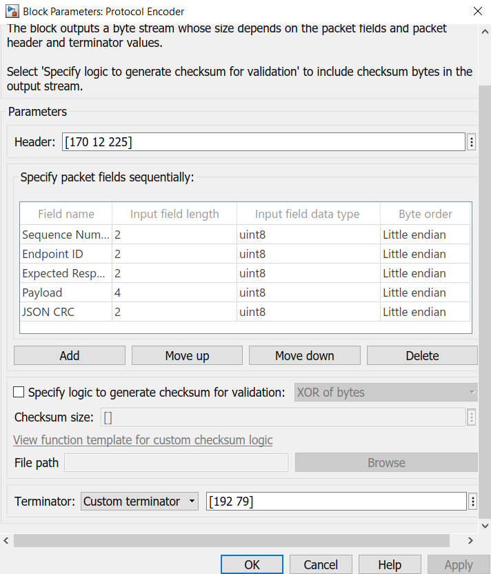
Further, on the Simulink program, it is asking for a header and terminator for the protocol encoder. Is this just the sync byte, packet length, and CRC8 for the header, and CRC16 for the terminator?
Any help here would be greatly appreciated. Thanks!
There are two versions of UART protocol supported by ODrive: ASCII and Native. The Arduino library uses the ASCII version, ODrivetool internally uses the native version. The sync bytes and crc stuff all relate to the native version.
Thanks for the response! Do you know how to check which of the protocols the ODrive is currently set to receive, or how to change between ASCII and native on the ODrive?
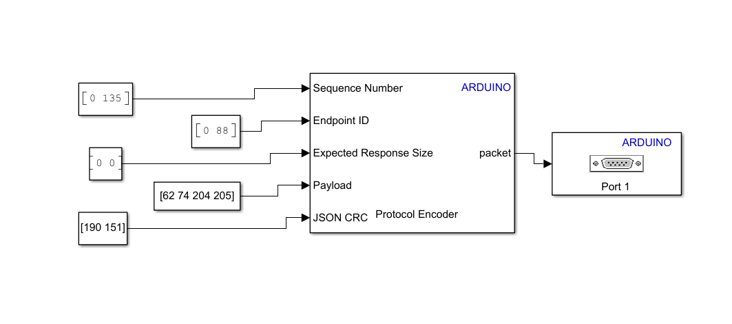
I am still having some trouble with the native protocol for my Simulink diagram. I understand that this is a forum for ODrive, so I wanted to keep my questions related to my implementation of the native protocol as I have implemented it in Simulink. For my velocity control stream, I have determined to send the following set of data:
This should correspond to a stream for velocity control of velocity 0.2. I have also made sure to set the following:
odrv0.config.uart0_protocol = STREAM_PROTOCOL_TYPE_FIBRE
Please see attached for my implementation in Simulink. Note that I have translated the above hex stream into uint8 since this is how Simulink wants my data. I have a few areas where I think my stream could be incorrect. First, I am unsure if my sequence number is correct. I was unsure if this matters, as based on previous forum posts it seems this is not needed. Second, I am unsure if my endpoint ID and JSON CRC is correct. I was not sure how to generate an endpoints definitions file, so I just used the json_crc and endpoint IDs in the odrive_endpoints.h file located on Github. If you have any suggestions for these or notice any other errors, that would be greatly appreciated. Thanks!
Edit:
It also occured to me, how does the odrive know whether we want it to control the motor on axis 1 or axis 0? I don’t recall any of these bytes in this stream being set for the motor destination.
First, if you want to use the native version, you should make sure you have firmware 0.5.1 installed. Higher versions are known to be buggy with that protocol.
But I’d suggest to use the ASCII version, it’s much simpler and already has arduino example code.
You get the endpoint ids from the json file that you can access from the odrive with endpoint 0. In that json file, there are separate endpoints for each axis.
You can get the json crc by running odrivetool --verbose. It will tell you the id and the crc is the upper 16 bits of that id.
Thanks for the clarification on the firmware version. I have actually tried the ASCII protocol as well with no luck. I have tried the following sequence of bytes, which I fed directly out of the serial port connected to the ODrive:
"v " 1 " " 0.4 " " 0.0 ‘\n’
Which in hex should look like this:
76 20 1 20 3E CC CC CD 20 00 00 00 00 0A
However, Simulink wants the data in uint8, so I have it like this:
[118 32 1 32 62 204 204 205 32 0 0 0 0 10]
I was just hoping you could tell me if my data packet is correct for the ASCII protocol. In particular, is the float 0.4 in the correct order (little endian vs big endian)? Should the motor number just be a 1, or should it be an ASCII 1? Can I just concatenate the whole message like this? I assume I should be able to, but so far there has been no movement on the ODrive using either of these protocols.
Based on the Arduino ODrive firmware, it appears the serial command for set_velocity is copying the binary data for the floats and the motor number. i.e. it essentially runs the following command:
This is why I was mixing the binary data and ASCII text. I don’t see anywhere the binary data is converted to ASCII text before being printed, either. Having said that, I have tried both ways, and neither way worked. Do you know if the floats are implemented correctly? Are there any other issues you can see?