I have 6 of those motors and i would like to make them to do cooperating movements for a robotic arm.
I am looking around how could i control those motors and i found the ODrive. I never heard again the ODrive, so i am looking for information about this.
I am thinking to use the ODrive to control a motor and Arduino Platform for the software.
It’s possible to do this?
How many ODrives should i have for 6 of the motors that i mention?
ODrive is presently (until v4 comes out) a dual-axis drive, so you’d need 3.
V4 will be single-axis, designed to minimise your wiring by placing the drive directly on the back of each motor.
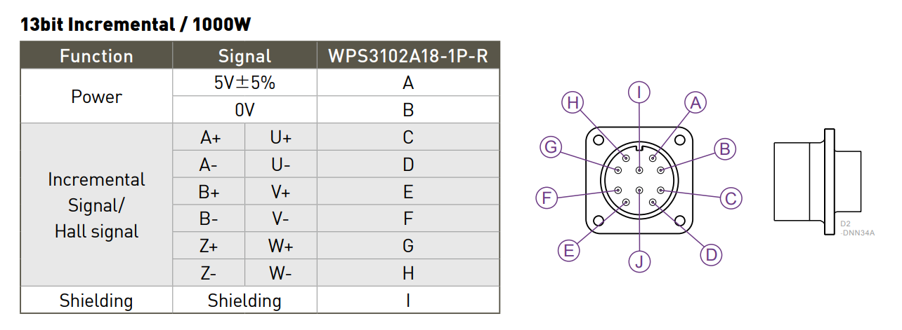
If you have +/- wires for each signal, then you have an industrial-style encoder with differential signals, designed for noise immunity over long distances.
ODrive takes single-ended signals. You can convert the signals with an RS-422 receiver chip like this one:
Do you mean, can you get away without an RS-422 receiver?
Maybe.
Some encoders will work if you connect all of the negative signal wires to GND, but it is definitely not guaranteed.
Try it.
You don’t need to connect the UVW wires - these are the Hall sensors. They are not needed if you have ABZ.
So, I was ordered and a RS-422 receiver ( cheap things ).
I will connect the A+ and A- on the input of the RS-422 receiver and then the output (from datasheets) I will connect on the A pin of ODrive? ( Same with B and Z )
There is something else should I do for this connection?
This is my first time that I will try to control a motor and now I am trying to learn things about them.
I completely understand what the ABZ do here but…
What the purpose of UWV?
I am trying to search online but I am confused
These are the Hall sensors. They are like a very low-resolution encoder, used by more simplistic drives. They have six states which repeat for each pole-pair, so their resolution is only 6 * N_pole_pairs counts per turn.
It is possible to run a brushless motor a bit like a brushed motor, using nothing more than Hall sensors and MOSFETs. The Hall sensor detects which phases need to be energised to form a basic six-step commutation sequence.
However, with six-step commutation, there is no torque control, so it is less efficient, less precise and less controllable than it can be with Field-Oriented Control (FOC).
FOC is a more advanced control scheme, using the precise position of the rotor and a PWM inverter to align the field so that it always produces a torque proportional to current, and it requires a high-resolution encoder.
The short answer is that Hall sensors (UVW) can be used for coarse control of a motor (e.g. for E-bikes etc) whereas FOC is more precise and can be used for motion control and precise positioning in robotics applications, but it requires a high-resolution encoder.
If you have both ABZ (incremental encoder) and UVW (Hall sensor), on both motor and drive, then ABZ is usually superior.
Some drives can accept both simultaneously. ODrive doesn’t officially support that.
The UWV hall sensors in servo motors are used to track the stages of communication so you don’t have to calibrate the motor from the start. Moving the motor to calibrate isn’t really feasible for most servo applications so a simple hall commutation encoder takes care of that. Then the actual FOC calculation is done with the incremental encoder.
Note that you need to disable the brake first to move the motor. Which needs 24V so you need a relay for this.
Hi Roiki1,
I’ve been searching for an answer for this question for so long. So glad to have stumbled upon your explanation. I think I kinda get it now. But i still have a more in depth question, hope you can answer
if you look at the wiring diagram above, you can see that ABZ and UVW signals are transmitted through the same set of cables. And I’m pretty sure UVW signals are used during start up, it’s called “phase initialization” by their software on PC. But once the motor is properly calibrated, ABZ signals are used to control the motor. So my question is, is it possible to mixed up the signals. Is there hardware tricks involed or you can simply connect the wires by pair (A+U, B+V, Z+W) and connect to the drive?
Also, is there a way to initalize the motor without UVW signals?
That doesn’t make much sense. It’s more likely the motor has two versions, one of which has a hall sensor and the other has quadrature. You can’t really run them on the same wires without some form of electronics being in the mix.
You’re right, it didn’t make much sense to me as well. I think some electronics must be involed.
Basically, my issue is that I’m using a generic motor (not from the same brand) to run with this brand driver (HIWIN D2 to be specific). My motor encoder output has both UVW and ABZ signals. However, the HIWIN D2 driver only has 9 pins for encoder input, as seen in the picture above. And I’m pretty sure their own motors’ (HIWIN motors) encoder also only have 9 pin as output.
Now they say something in their manual that puzzled me and kinda made me think that they used some tricks in their hardware so that they can work off 9 pins for encoder communication.
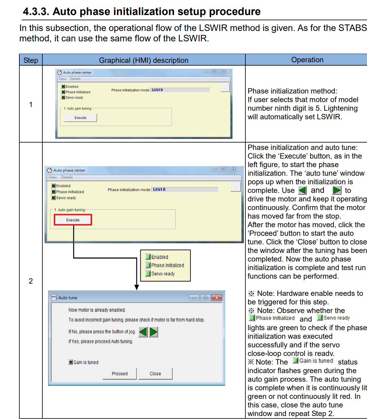
Here they talk about phase initalization, which is the step I failed at.
So i think my question is, do you absolutely need UVW signal for motor phasing or you can do it just fine with ABZ singal alone? If yes you need UVW signals then they certainly did something unique to their hardware.
Link to the full manual: https://www.hiwin.us/wp-content/uploads/d2_drive_user_manual.pdf
You can do phase searching with incremental encoders. That’s what odrive does. The hall sensors can be used to skip the phase searching for incremental encoders which is required for the drive to function.
Otherwise I have no idea, the drive doesn’t seem to have hall inputs.
I see. Thanks for your explanation. Do you know where I can read up more about phase searching using incremental encoders in AC servos? Tried to google but can’t find anything useful.
You can read the odrive docs for info on how the odrive does it. The fundamentals are the same in most servo applications. Or you can read on the theory of field oriented control and it’s applications if you want to delve into the weeds of it.


 ).
).