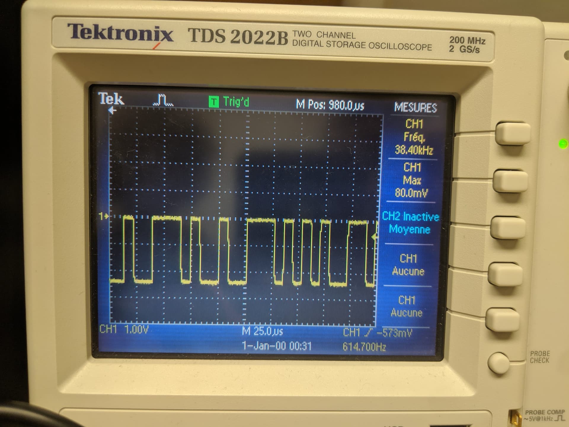
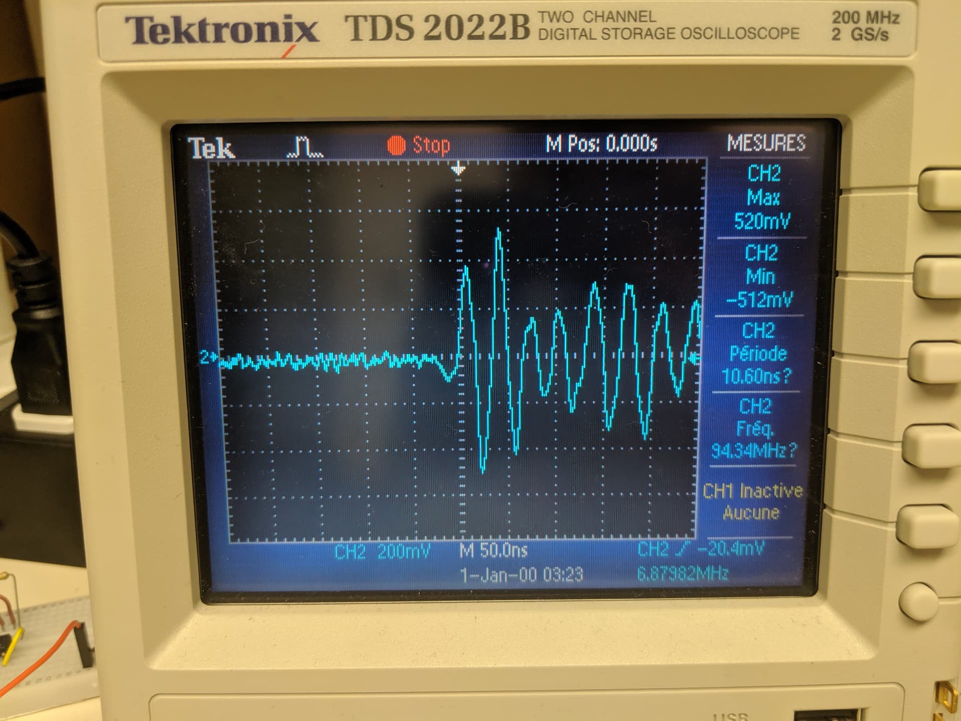
After putting the scope of the oscilloscope on the Tx, I get this:
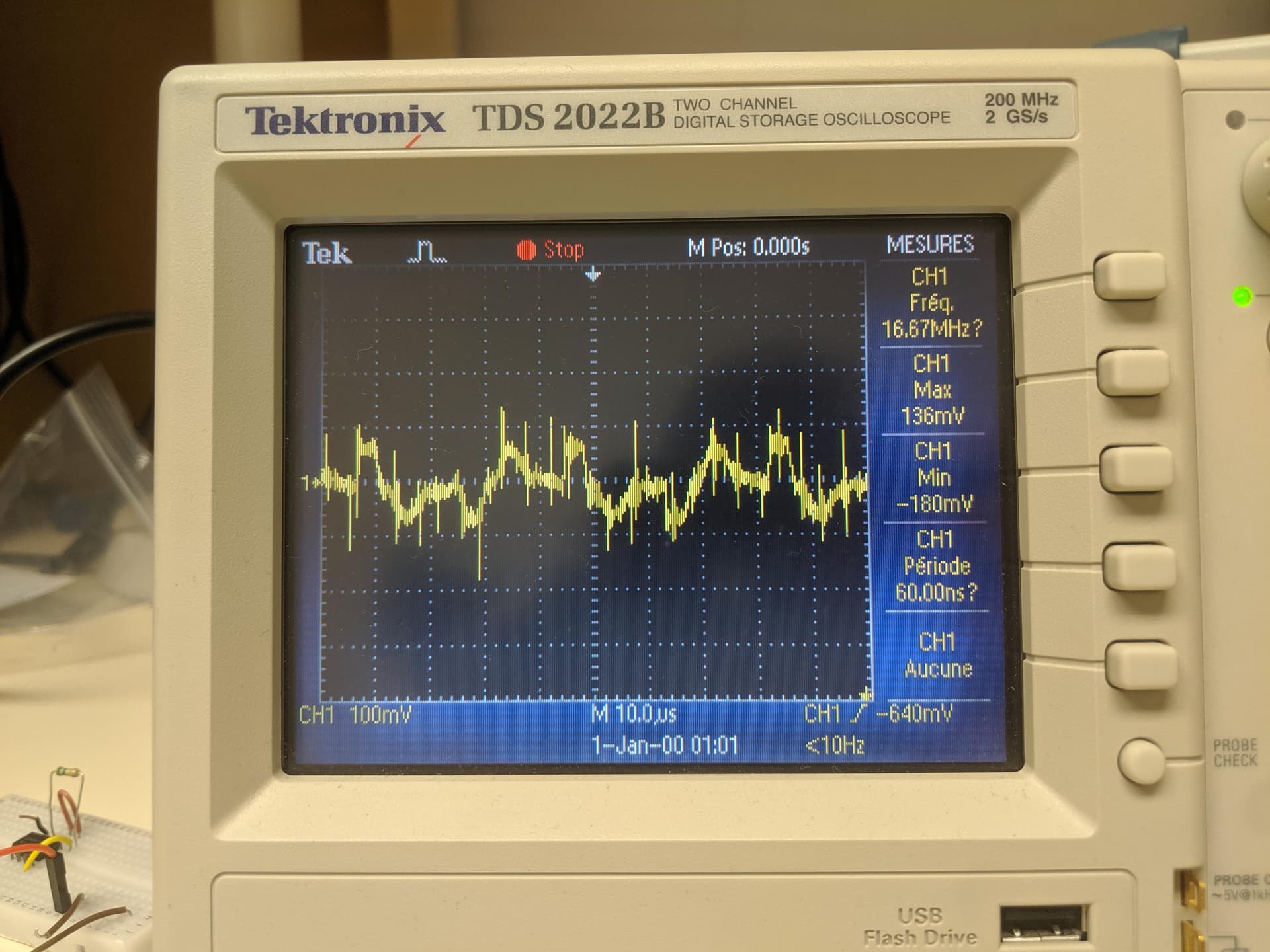
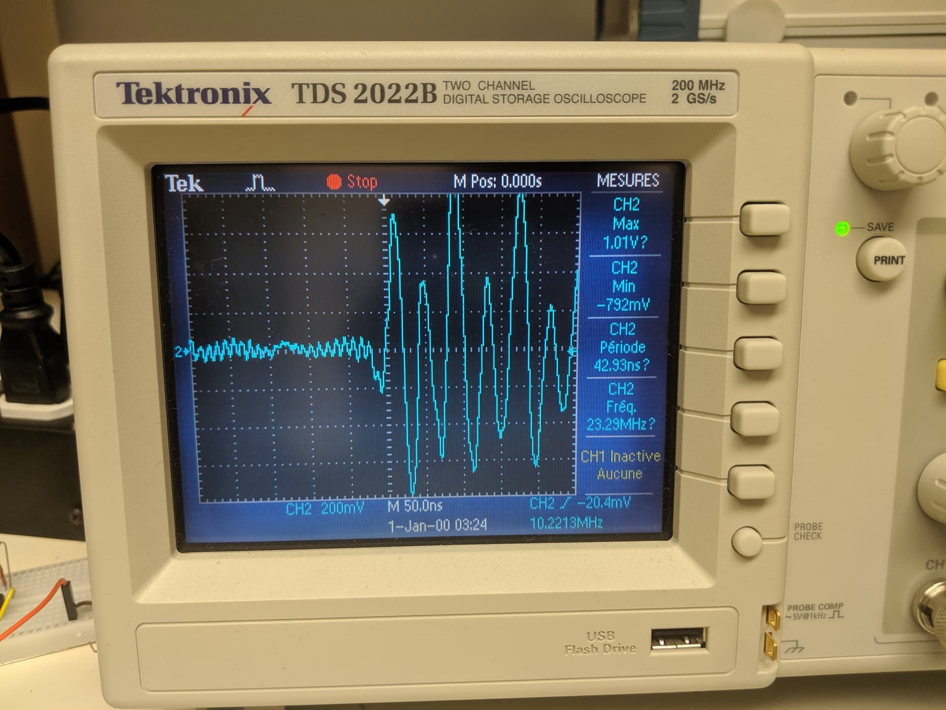
And after putting the scope on the Rx, I get something very noisy but after pressing on “stop” on the oscilloscope, I have this:
This is the code that I am using on the Arduino IDE:
#include <ODriveUART.h>
// Documentation for this example can be found here:
// Controlling ODrive from an Arduino via UART — ODrive Documentation 0.6.9 documentation
////////////////////////////////
// Set up serial pins to the ODrive
////////////////////////////////
// Below are some sample configurations.
// You can comment out the default one and uncomment the one you wish to use.
// You can of course use something different if you like
// Don’t forget to also connect ODrive ISOVDD and ISOGND to Arduino 3.3V/5V and GND.
// Arduino without spare serial ports (such as Arduino UNO) have to use software serial.
// Note that this is implemented poorly and can lead to wrong data sent or read.
// pin 8: RX - connect to ODrive TX
// pin 9: TX - connect to ODrive RX
// SoftwareSerial odrive_serial(8, 9);
// int baudrate = 19200; // Must match what you configure on the ODrive (see docs for details)
// Teensy 3 and 4 (all versions) - Serial1
// pin 0: RX - connect to ODrive TX
// pin 1: TX - connect to ODrive RX
// See Teensyduino: Using the UART (real serial) with Teensy on the Arduino IDE for other options on Teensy
HardwareSerial& odrive_serial = Serial2;
int baudrate = 115200; // Must match what you configure on the ODrive (see docs for details)
// Arduino Mega or Due - Serial1
// pin 19: RX - connect to ODrive TX
// pin 18: TX - connect to ODrive RX
// See Serial - Arduino Reference for other options
// HardwareSerial& odrive_serial = Serial1;
// int baudrate = 115200; // Must match what you configure on the ODrive (see docs for details)
ODriveUART odrive(odrive_serial);
void setup() {
odrive_serial.begin(baudrate);
Serial.begin(115200); // Serial to PC
delay(10);
Serial.println(“Waiting for ODrive…”);
while (odrive.getState() == AXIS_STATE_UNDEFINED) {
delay(100);
}
Serial.println(“found ODrive”);
Serial.print("DC voltage: ");
Serial.println(odrive.getParameterAsFloat(“vbus_voltage”));
Serial.println(“Enabling closed loop control…”);
while (odrive.getState() != AXIS_STATE_CLOSED_LOOP_CONTROL) {
odrive.clearErrors();
odrive.setState(AXIS_STATE_CLOSED_LOOP_CONTROL);
delay(10);
}
Serial.println(“ODrive running!”);
}
void loop() {
float SINE_PERIOD = 2.0f; // Period of the position command sine wave in seconds
float t = 0.001 * millis();
float phase = t * (TWO_PI / SINE_PERIOD);
odrive.setPosition(
sin(phase), // position
cos(phase) * (TWO_PI / SINE_PERIOD) // velocity feedforward (optional)
);
ODriveFeedback feedback = odrive.getFeedback();
Serial.print(“pos:”);
Serial.print(feedback.pos);
Serial.print(", ");
Serial.print(“vel:”);
Serial.print(feedback.vel);
Serial.println();
}