Thanks marine from space. I’m getting quite excited about trying. If all were to fail I can always replace with a stepper, so I see only positive things in trying the Odrive with a lot of potential improvement over those steppers
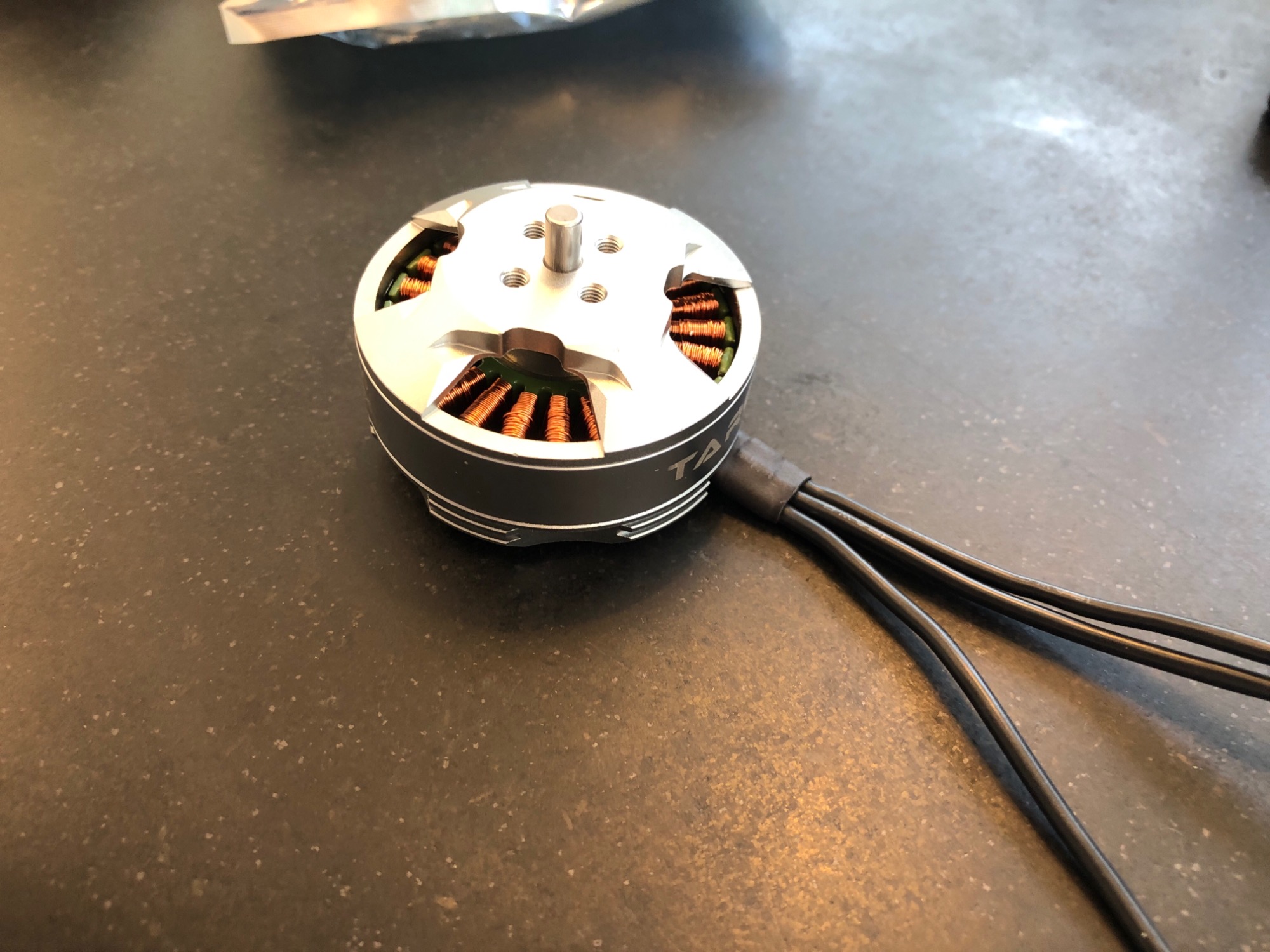
I can get a good deal on Tarot 6S 380KV 4008 4108 motors. They seem perfect for the job (?) and documented on Odrive. But I’m a clear novice and wonder how to:
connect the encoder in the back when it doesn’t have a second shaft sticking out? This is obviously very novice question, but I thought I’d ask anyways.
if it makes sense to mount the motor with a coupling as it doesn’t have a shaft coming out either and I fear misalignment with an adapter with shaft. Does anyone have an example setup perhaps on a Tarot?
I’ve also been thinking about the input filter for the step / dir. I found following on the step / dir interface.
There is also a config variable called <axis>.config.counts_per_step , which specifies how many encoder counts a “step” corresponds to. It can be any floating point value. The maximum step rate is pending tests, but it should handle at least 50kHz. If you want to test it, please be aware that the failure mode on too high step rates is expected to be that the motors shuts down and coasts.
So I wonder at what frequency the Odrive drives the Servos? Probably higher than that, so the input filter makes sense for sure.
So I didn’t give it too much thought at first, but what is really meant with a second order filter? Is the filter meant to upsample the signal to the Odrive control frequency?
I ask as I imagine stepper drivers do something similar with the incomming signal from the controller…
Most definitely, I am using ODrive at 12v for CNC and it doesn’t even remotely get warm. I’m using an Arduino Mega 2560 only and controlling the ODrive over serial, not step/dir.
I did exactly this, I have a bench power supply connected directly to a 12v lead acid battery (75Ah) and this connected to the ODrive (power in port) with its supplied resistor in the brake resistor port. I get around 65000 cps max velocity (with AMT-102, 8192cpr) without the battery and over 300,000 cps with the battery.
Also, without the battery I had a lot of current unstable messages due to low voltage dropout, something I never get on batteries.
Now I have my ODrive CNC machine running off 12v batteries and a 50W Solar Panel ;-D.
You wouldn’t connect it in place of the resistor, you’d connect it as you originally suggested, in parallel with the power supply. You can leave the brake resistor in place, and just set its resistance value to 0 in the config, which means it won’t use it, and will instead send regen energy to the battery.
Using a bench power supply you can adjust the voltage and current limit so that it doesn’t overcharge the battery, although a dedicated lead-acid trickle charger might be better (and cheaper). And a lead-acid battery won’t explode in flames when you overcharge it. (it does give off a bit of Hydrogen gas, though!)
The battery will also prevent the voltage rising too much on regen braking, which would otherwise bork your power supply. So I can see that it does make sense (although a large capacitor would also do fine). 75Ah seems a bit overkill though!
You are right - it can help precision in some cases. I just realised why on this thread:
If you are getting to the point where you need a higher current control bandwith than the controller can provide (i.e. >4kHz) then adding inertia can help, by essentially making the motor more sluggish to move so you don’t need such fast reactions from the controller. But it’s probably an unusual case for ODrive, which runs at low voltages where the inductance is probably the biggest limiting factor for current control bandwidth.
I’m checking your youtube movies Dev, thans for posting. Really interesting and helpful.
So cool to know that as Robo found, inertia can help to keep the motor from cogging and I imagine it can also help to improve the smoothness of operation when the Step / Dir is not really giving a high enough (frequent) pulse train. I’m now trying to find out how many steps I may expect when running an SKR with Klipper. But so easy to find the info though.
Also I’m still very interested in the filter function on the Odrive. Hope @Wetmelon can share more insight if it is indeed an upsampling of the pulse train or if the second order filter has another purpose.
And I hope I can fit an encoder on the Tarot motor?
Ok I did some more homework on my current Duet3 and I can expect to send up 120k pulses per second to the Odrive and even more if I could use the driver output wires (the A B etc) if I put in some kind of logic electronics in to get the step / dir back and eat the current?
But I would think 120k pulses per sec would be enough as it will give me a max speed of about 500mm/s print speed on a 8192 encoder sending a step for each countbwhich is more then enough right?
Ok I bought Tarot 4108 laat week and just now the Odrive. I’m still puzzling on the power supply a bit as there are so many options though. But at least now I understand what can be used in order not to blow up batteries and Odrives
Still figured what encoder to buy. To be honest I would like it best to place it on the pulley then on motor at some point as discussed elsewhere on the forum.
I recogn I’d have about 10 to 15 rotations a sec maximum. It is normal to zero 3D printers, so that would be fine for me.
Encoder on a pulley is a bad idea. If the belt slips over time your machine will go out of position, lose torque, and eventually the drive will fail to commutate the motor. You could also get into a really nasty dynamic oscillation if sudden acceleration of the motor causes the belt to stretch, even by a tiny bit.
Can’t you mount something like an AS5047p to the back of the motor?
I will start with encoder on the shaft die sure. Yet in the end I’d like to put it on the pulley. Gate belts don’t slip with they teeth and all and are (relatively) stiff. I computed first resonance frequency of the setup in the order of 120Hz. Should be possible to get a stable feedback on it would be my guess abs in the other thread I read the motor and pulley could get out of sync multiple degrees so feels like possible in principle? But you are right, I should start with the basics!
What is the best way to glue (?) a magnet on the rear end shaft of the motor? And how important is alignment of the magnet on the center of the shaft for encoder performance?
In my experience, the alignment of the magnet is not very important at all! The sensors are extremely tolerant of a magnet that has been superglued on the piss, or a sensor that is mounted slightly off axis.
Superglue tends to work well for me, because I can remove it if necessary. Maybe for speeds of 10krpm+ you might want to be more careful, but only to avoid the magnet pinging off.
Interesting… What failure do you get? I’ve recently had SPI COM errors due to a fault flag from the encoder, but that seems entirely unrelated to motion ie it measures perfectly when I turn the motor by hand, but recently when I turn the motors on, I get the SPI error until I power cycle the encoder itself. Previously they all worked fine. Probably i need to tie MOSI to 3v3.
One motor even has just a 3mm magnet shoved inside a rubber grommet, with the AMS board on a couple of nylon standoffs. No issue with measurement at all.
I was getting all sorts of nonsense, but maybe I should revisit it since I’ve since discovered my setup doesn’t work unless I configure the software just so
I’m about to buy a power supply for the motors but wonder if say a Meanwell 240W supply in 24V or 48V for the Tarot 4108? And is 240W to dunne just the two motors enough (motors have to pull max 600gr each without a gearbox and a pulley that does 35mm belt motion on one revolution?
I also do hard to find the AS5047P here in The Netherlands… And while reading I had the impression it “only” gives 4096 pulses per rev?
It gives 16384cpr in SPI mode. Its default setting I believe is to send only 4096cpr over the incremental A/B/I interface, but it is possible to change that with some SPI configuration commands (you’d need to write your own code to do this, not something ODrive supports - i’d recommend just use SPI directly as an absolute encoder)
240W is plenty for full torque, but not enough for both full torque and full speed at the same time, (which you probably don’t need).
I’d go with the 48V PSU and the 56V ODrive always - it’s better to have the voltage headroom for control performance, even if you don’t need the max speed at 48V.


 .
.
