Current setpoint jumps to maximum when velocity setpoint is above a certain level

Hi all,

So we’ve been using a custom integration of the ODrive v3.5 at work for the past several months and it has worked quite well. Recently we ran into a new issue and I was wondering if I might be able to get some insight from the community as to what the problem might be.

For background our FW version is ODrive FW v0.4.10 with a few minor patches. Our motor selection is the Maxon EC 45 Flat 70W (datasheet) with Hall effect sensors and no encoder. Since this is a lower current motor, we have adjusted the value of the current sense resistors to 15mOhm to try and improve the SNR for current sensing. The firmware has been patched accordingly. We typically run the motor in velocity control mode. We followed the hoverboard motor setup guide initially since that was closest to our application. In particular, we set the following configuration values:

odrv0.axisN.motor.config.pole_pairs = 8
odrv0.axisN.motor.config.current_control_bandwidth = 100
odrv0.axis0.motor.config.requested_current_range = 10
odrv0.axisN.encoder.config.mode = ENCODER_MODE_HALL
odrv0.axisN.encoder.config.cpr = 48
odrv0.axisN.encoder.config.bandwidth = 100
odrv0.axisN.controller.config.vel_limit = 5000

(I can provide more details regarding the configuration later when I have access to the hardware to take a look at it again.)

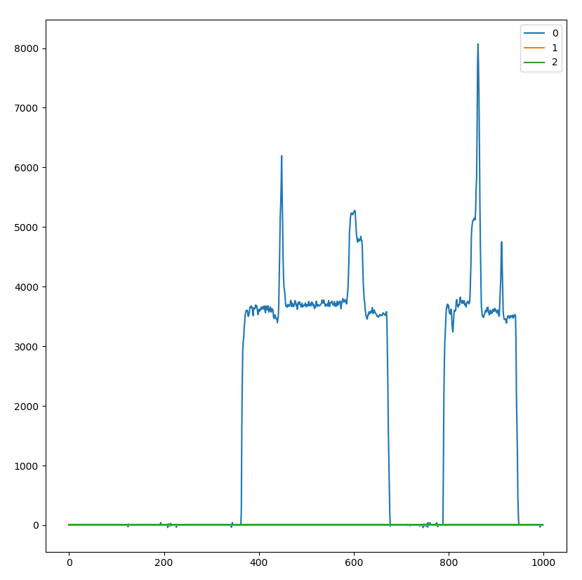
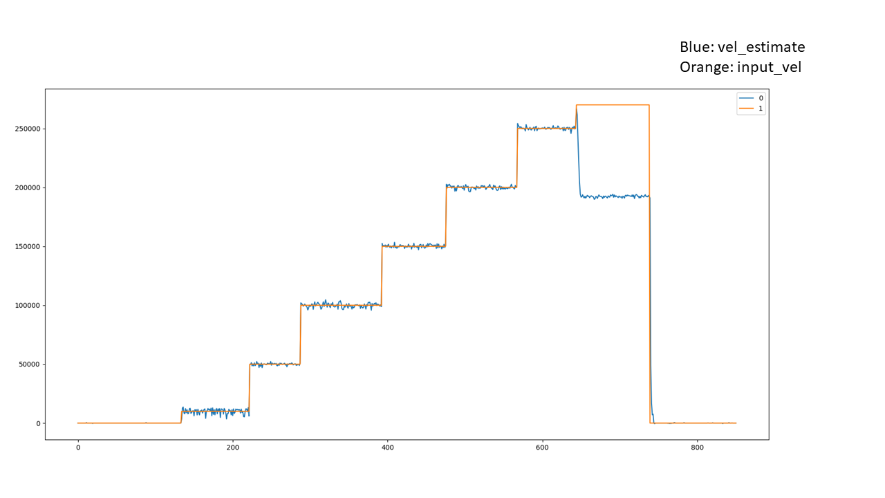
Up until now we have run the motors at a maximum vel_setpoint of 2500. Today we tried to run the motors at a higher velocity and we got an interesting result. See the attached plots below:

(I had a second image, but I guess new users are only allowed one image per post.)

In both plots, the blue trace is the velocity setpoint, the orange trace is the estimated velocity, and the green trace is the Iq_setpoint in mA. The maximum current has been set to 5.5A. Once the velocity setpoint reaches a certain threshold (somewhere around 3700 counts / rev), the Iq_setpoint jumps to the maximum allowed value and the velocity control loop breaks down. The velocity estimate seemed to drop to the same value each time and motor speed seemed to roughly match the reported estimate. The only way to clear the drive out of this state is to lower the velocity setpoint back down below where it dropped in the failure event. Surprisingly, I haven’t picked up any ODrive error codes during this event. This is very strange behavior, and we only have a few rough guesses as to what the root cause could be.

  • We’ve experience some problems with noise on the current sense lines, so it’s possible that the current control loop or phase current measurement is unstable and causing this problem?

  • It almost looks as if the velocity estimation can’t track velocity beyond a certain value. Maybe we’re hitting some sort of upper bound on the velocity measurement due to the Hall effect sensors / lack of encoder / lower encoder bandwidth?

For what its worth, we tried testing a motor with the ESC sold by Maxon and we were able to get the motor to a much higher RPM, so we know it’s not an inherit limitation in the motor. We’re going to try with an official ODrive board tomorrow to see if the problem is isolated to our custom board, so I’ll report back if we get any information from that testing.

Any thoughts as to what the root cause might be here? Suggestions for things that we should test? I’m intrigued by this problem as I’ve not seen anything quite like it before in working with the ODrive. Thanks for any assistance!

Here’s the second image that was supposed to be in the original post:

1 Like

It looks to me like there is a limit somewhere that is overruling the current controller. Does changing the velocity limit in the trapezoidal trajectory controller change the behavior?

1 Like

@Riewert

I checked the trapezoidal trajectory controller velocity limit and it’s still set at the default value of 20000 counts / s, so I don’t think this is the source of the problem. I also looked through the firmware and it doesn’t seem like the trapezoidal trajectory planner should have any impact during velocity control.

One of my coworkers was doing some more research and we found this post: ODrive for PMSM. Can anyone confirm is that the peak line-line voltage for a 24V ODrive would still be 16.6V? I guess the only thing that might have changed would be the amount of modulation time left open for current sensing.

Hmmm, then I have no clue. Try asking on discord. Am interested what the solution is.

So we ruled out the velocity estimation failing. Using a “drill test,” we were able to generate the following plot:

The blue trace is the estimated velocity of the motor. We set the requested state to AXIS_STATE_IDLE before testing so that we would not damage the board. The plot clearly shows the motor tracking velocity well above our desired range, so it seems unlikely that the velocity estimation is failing. The spikes in the graph are due to the fact that we had poor engagement between the motor shaft and the “drill” and so we could not safely sustain a high velocity for very long.

I’m somewhat stumped as to what the problem is here, unless it’s a BEMF issue. We still need to test with a stock ODrive and we also have a slightly different motor on order that may perform better.

Which of the motors in that datasheet do you have? What is your bus voltage?
The most plausible case to me is that you are running into the modulation/voltage limit. A tell-tale sign is if Iq_setpoint and Iq_measured become very different from each other, you can plot them and check.

Bus voltage is 24V. Motor P/N is 411812. We will try that test; thanks for the suggestion! Is there any documentation that discusses the modulation/voltage limit?

Did anyone determine a solution to this? I’m experiencing the same behavior with my stock v3.6 - 56V ODrive
With error, in this case a velocity setpoint set above the motor’s max velocity, the current setpoint jumps to the limit and the velocity drops significantly. All velocity limits have been disabled.

A behavior that may be related, in current control mode if I ramp up the current setpoint the measured velocity will also decrease.

All tests are just under rotor load. Any ideas? Thanks in advance!

In my team’s experience we found that this condition indicated that the ODrive was essentially power limited. As Oskar suggested, the plots for Iq_setpoint and Iq_measured also diverged. Here’s my understanding of the situation:

  • If you look at the block diagram for the ODrive control loop, you see that the velocity controller cascades into the current controller which drives the motor current by applying different voltages to the motor phases.

  • The ODrive can only apply a maximum line-line peak voltage of sqrt(3)/2 * 0.8 * Vbus due to the math behind SVM and the ODrive current sensing methods (see here). In our case, that limit was 24V * 0.8 * 0.87 ~= 16.7V.

  • The velocity controller adjusts the current setpoint which drives the motor current by setting the phase voltages. If the phase voltage required to meet the current and velocity requirements is higher than that limit, the ODrive clamps at maximum output. This causes the current loop and velocity loop to both “fail” (although no errors are thrown directly).

  • Since the velocity setpoint is not being met, the velocity loop increases the current setpoint until it hits the current setpoint limit. But the current loop is already at maximum output because the ODrive cannot increase the phase votlage further. As a result, Iq_setpoint jumps to the limit, Iq_measured sits at the maximum output, and the velocity plot behaves as shown in the pictures in this thread.

  • To confirm that the ODrive was power limited, my team tried increasing the DC bus voltage from 24V up to at least 30V. (I don’t remember the specific number as this was several months ago. We did ensure that the higher bus voltage did not exceed the maximum voltage rating for any of the components on the board.) With an increased bus voltage, we were able to get the motor to spin at the higher velocity that we were targeting without errors.

I would try plotting your Iq_setpoint and Iq_measured next to see if you are also power limited. Unfortunately I’m not sure if your options are that great if that is the case. We ended up changing other portions of our system mechanically so that the higher velocity was not necessary, but our other thoughts were to increase the bus voltage or find a different motor with better physical characteristics for our application.

Very good writeup, and I would say is the correct analysis. To verify, we would need to know the Kv rating of the motor, and the speed we are trying to reach, and the bus voltage.
Or as suggested, we can try varying the bus voltage and see what happens.

That said, @turndog posted this picture in discord, and it has every single symptom:

  • Current setpoint and measured diverges
  • Velocity controller’s output hits current limit
  • Velocity does not keep up (and actually falls a little (this is because the voltage angle gets disturbed due to the saturations))
  • We also see an interesting velocity controller windup recovery in the circled region as the voltage angle recovers

Firstly, thank you @Domenic_Gecko and @madcowswe for the detailed responses. I did test with 48V and did get approximately double the maximum velocity, with the same sudden drop in velocity when the Iq_setpoint shot up to its max from sending it an impossible velocity set point.

@Domenic_Gecko Interesting… I wasn’t aware of the 20% decrease due to the current sensing. That would explain the increase in velocity with the same voltage from another controller I used for testing. @madcowswe Any thoughts on using three current shunts on a future version?

@madcowswe Could you please explain the disturbance of the voltage angle when the current limit is saturated a little further?

I did an iq_setpoint sweep and found that the measured current is indirectly proportional to the measured velocity. The velocity measured when the current setpoint spiked due to error in the velocity mode example was the same velocity measured when the current setpoint was set to the max in current mode.

A good explanation of the relationship of velocity and magnetic flux density at no load is found on page 34 of the Electric Motors and Drives Text (PDF warning). From the reading I did and the current sweep experiment, I figured the decrease in velocity with the increased current at no load was due to a field strengthening effect.

@Domenic_Gecko Out of curiosity, was your motor loaded during your experiment or was it at rotor load?

Yes likely field strengthening (due to loss of voltage advance angle). You can check by also plotting motor.current_control.Id_measured. If it is a positive value, it is confirmed.

The reason this happens is because the voltage saturation is a radial clip of voltage magnitude. If there is a large q-axis voltage request (to drive a dI/dt in the q axis due to the large current error), but the voltage is clipping, it will reduce the effective voltage advance angle. See diagram:

This more +d voltage than optimal leads to a more +d current, arriving at an equilibrium like so:

image

As we can see the vertical V_L component (coming from +d current) is eating away our back-emf capacity, hence our speed.
The effect is most pronounced with large inductance motor and high speeds.

@madcowswe Interesting… Thanks for the detailed explanation! It makes a lot of sense.