yeah i saw some single drive version. for me the size of the pcb is critical thats why went with the custom design.
additionally, tried to improve the thermal dissipation by placing heatsinks closer to copper (on the opposite side) instead of on top of the components.
i am also using 4 layer pcb. but my placement and layer topology is different from the original odrive. i have used top layer for signals + high current paths, layer 2 for a solid GND. layer 3 for power rails. and layer 4 again for signals+high current paths. you may checkout the pdfs in the output folder.
Hi azmatb!
I am impressed by your work! Great!
I saw your manufacturing plans and that the pcb would fit into my 90mm linear actuators for a maybe next version “actuator ready for USB”. That would be amazing!
So if you need help with mechanical stuff, let me know!
hi guys.should have updated earlier but i was able to assemble two PCBs and test them. one of them didnt work due to poor soldering but the other unit seems to work as expected. i was able to:
Flash the firmware as well as communicate with the odrivetool.
connected a BLDC motor and was able to calibrate it. the motor moved a bit and them stopped with a beep.
havent yet tested full motion as i need to connect the encoder. but i think it should work also.
whats the quickest way to test the motor without encoder. i can try that. other than that the pcb seems to work and there were no shorts/black smokes etc. as a result the release v1.0.0 is good to use https://github.com/azmat-bilal/bldc_motor_controller_pcb/releases
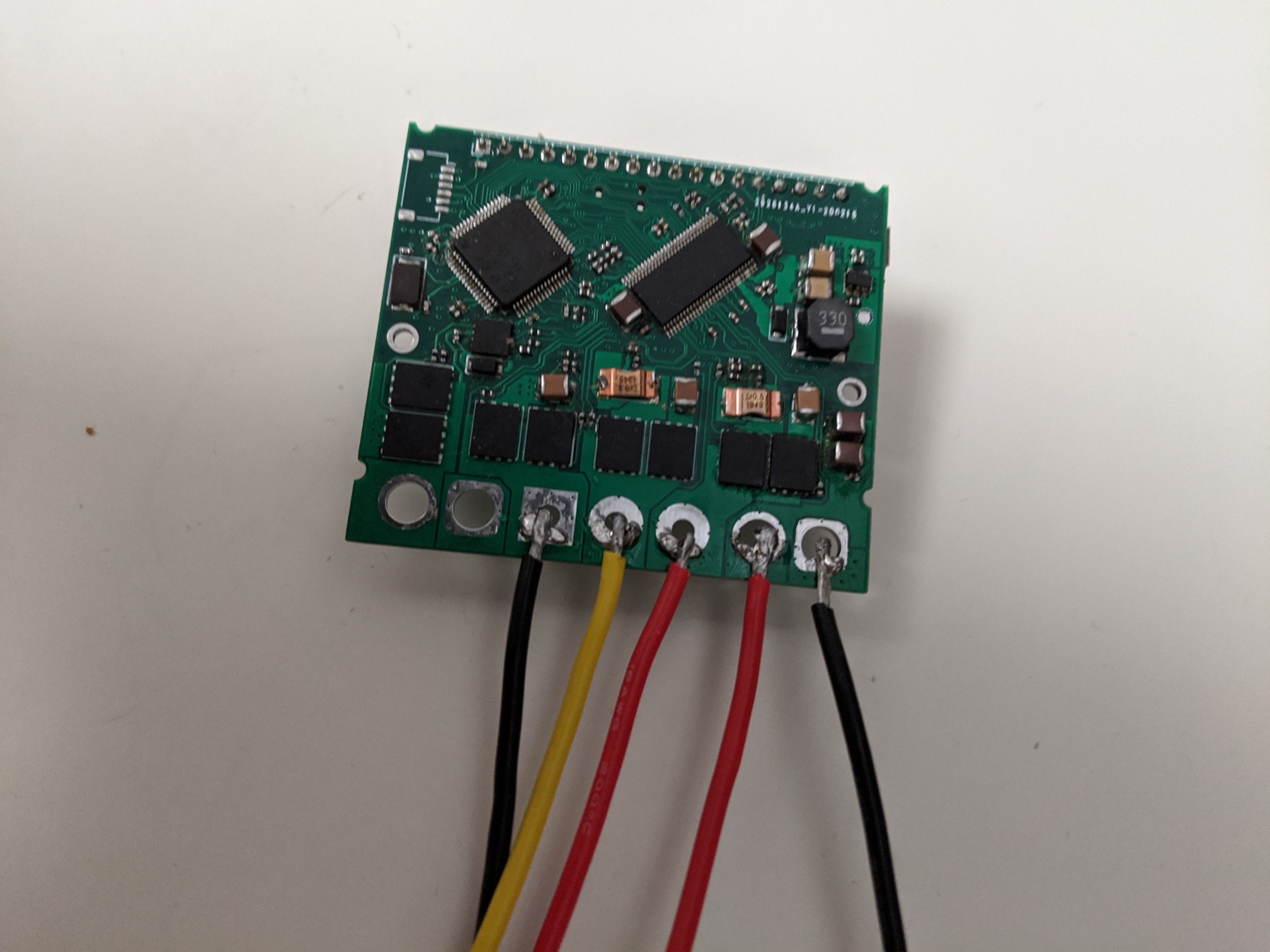
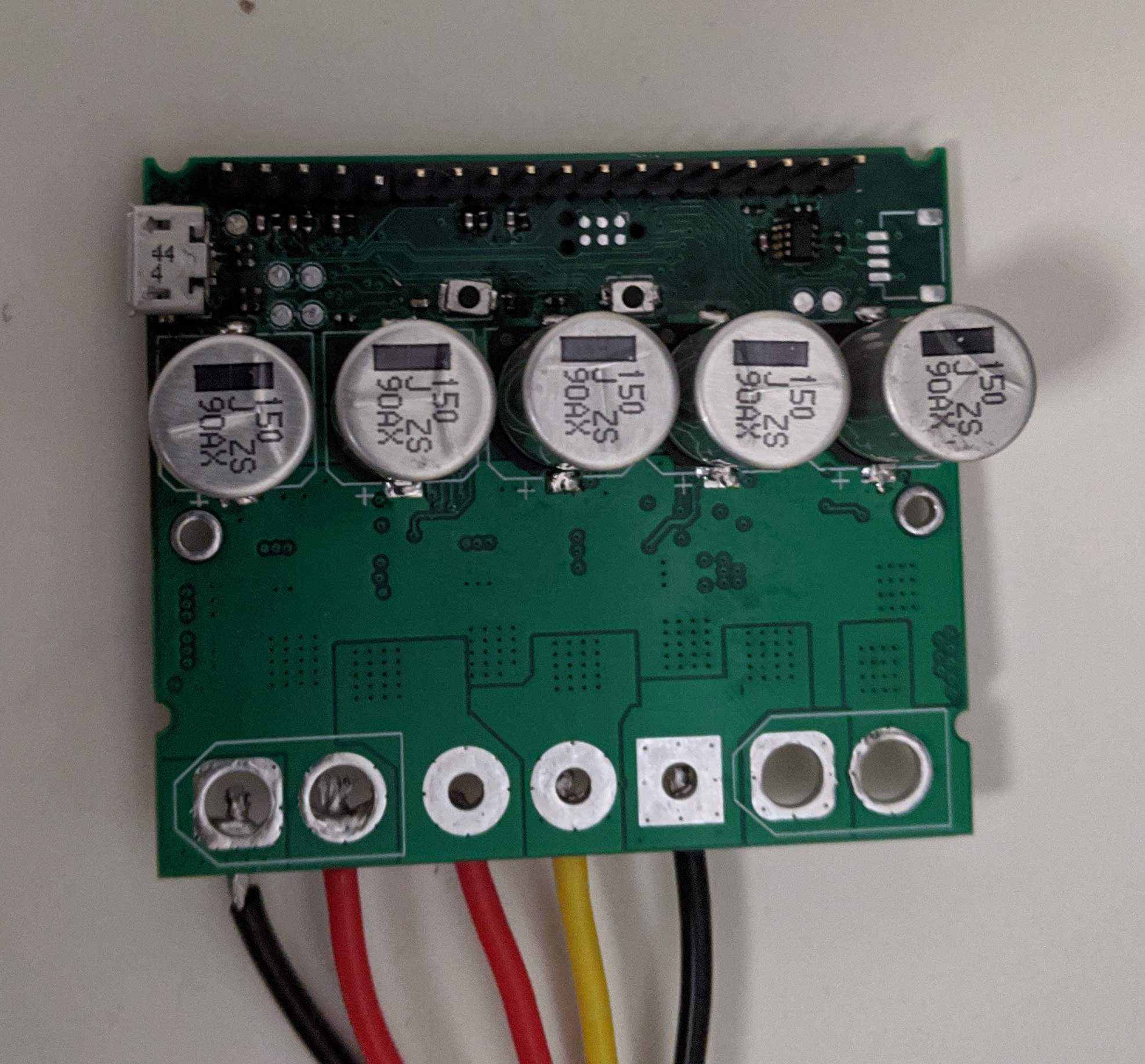
here is an image of the assembled pcb. though it looks dirty due to too much flux.
i used mosfets with higher current rating and therefore was able to use only one instead of two. with proper thermal management (use of heat sinks) these mosfets should be able to handle more current than the original design. once again i havent tested the design thoroughly enough to validate all the edge cases( mosfet gate charge timing etc) and power limits but so far it looks good.
i am actually away from my workshop due to covid19 so couldnt test the boards further.
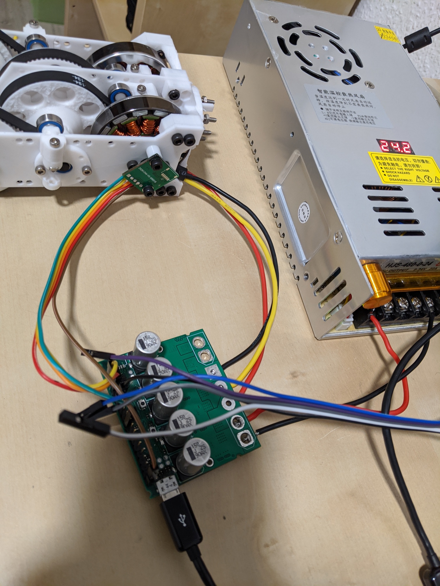
Hi Guys, i was finally able to test the pcb with an encoder. everything including the encoder pcb is functional. i was able to calibrate and move the motor to the desired pos using odrv0.axis0.controller.move_to_pos().
there was one issue where the odrivetool was not able to communicate with the pcb and only when i connect the programmer i was able to communicate. but upon further debugging it turns out if i only connect the GND of the programmer it works. this means there is probably a missing solder connection on the USB connector (as it was very hard to solder by hand) and the programmer was able fix this missing connection between the pcb GND to the GND of the computer. with proper soldering this shouldnt happen.
i ordered parts for only two boards, i think it was roughly 150euro for 2x controller pcbs and 2x encoder pcbs. its not very economical at low volumes. but if you need a smaller pcb or are ordering more than 4-5 controller boards then its better. uploading the mouser ordered cart to the repo for reference.
I’ve read the whole thread, amazing work! I have a small issue that you might know how to resolve.
I have been using a modified one axis ODrive (based on firmware 3.4-24v) with the odrive tool v4.12. The only thing that was modified in the “custom” firmware, was the shunt resistors i replaced with 0.015ohm. Everything worked quite well, until i updated the odrive tool to v5.1. I noticed new attributes and methods. This lead me to update the firmware with the latest version. Once again, i only modified the shunt resistor values to 0.015ohm, and i expected everything to work as before.
Unfortunately, it did not. I tried to run the simple command odrv0.axis0.requested_state = AXIS_STATE_FULL_CALIBRATION_SEQUENCE, but nothing moved.
Do you have any idea about the firmware changes? Is there something in the firmware that requires the second axis? Is there some sort of “ping” the processor expects from the second axis?
Hi
sorry for the late reply. just checking today. havent looked into the firmware so cant say for sure if thats the issue or not. but changing the resistor values definitely changes the voltage drop across it and therefore the current sense readings. if you can change the current limit then maybe a quick test can be setting the max current limit and seeing if it works.