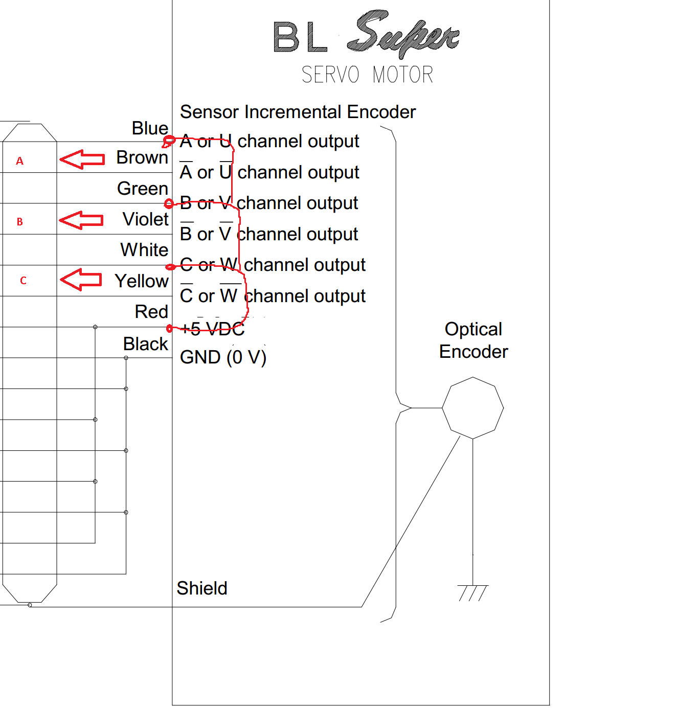
Has anyone tried to connect a BLDC motor with an encoder that has differential (+ & -) outputs for each phase?
In the past I have simply wired the positive side to VCC and the negative to the endpoint,
That does not appear to be working on the Odrive.
I can see the pulses on my scope peaking around 2.8775v.
Is this high enough to trigger the input opto?
Should I just input a higher clean voltage from 5V?
Like this…
Just checked the schematic. The signals are all 3.3V based, but the encoder connector J4 has a 5V pin for powering each encoder. There is no opto on this board, the ENC pins are tied directly to the STM32! I don’t know if they’re 5V tolerant, but I wouldn’t risk it. The ENC pins are pulled up to 3.3V through a 3.3k ohm resistor to accommodate open collector encoders. 2.8775V should be more than enough to trigger it…
Can you give us more information on the motor (pole pairs, etc), and the encoder (ppr)?
I should have looked deeper at the schematic, I’m glad I did not try it blindly.
For the motor, it is a BL Super P5 60 watt.
I also have a few hundred 400 watt models.
As best as I can determine both models have 4 pole pairs with a 2000 line/rev encoder.
Correct, the motor runs in encoderless mode but when I connect everything up with positives to VCC and endpoints to negative I get nothing, no driver whine at all. The 400 watt model weighs about 12lbs! They are all surplus from 1998. Sadly they were stored somewhat poorly, quite a few have encoders that go tits up as soon as they see voltage.
I have tested this particular motor on a 100 amp PY amplifier, and was able to get it to auto-tune (surprisingly) and move far more than the rated load.
That’s very strange. All I can think is to double check you’ve set the “control_mode” value correctly, and then to connect the USB debugger to the drive and check for any errors using the python script and API.
In most cases I have seen when interfacing differential signals to signle-ended inputs, it would be terminating the negative side to GND, and wiring the positive signal to the single-ended inputs. The rationale is that it’s common to use GND as the shared reference. Is there any reason you have elected to do it the other way around?
All micro-controller inputs (GPIO, encoder, etc.) are 5V tolerant on V3.3.