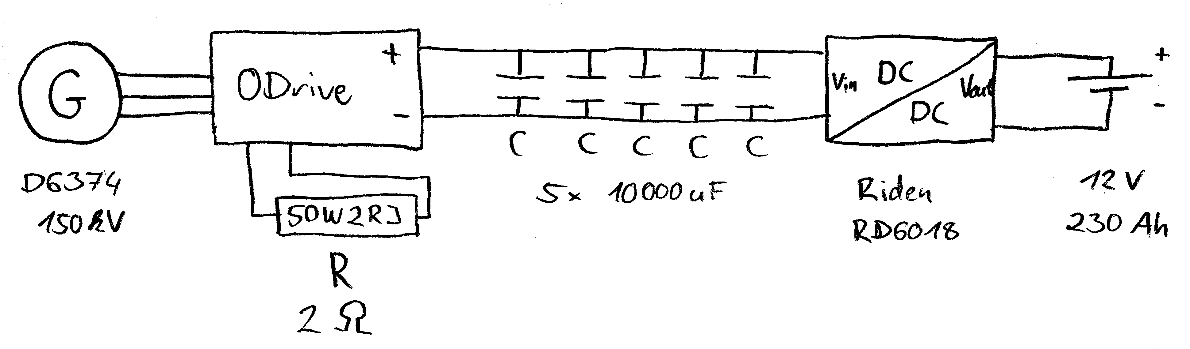
I connected the flywheel of my rowing machine to the D6374 150kv dual shaft motor with a tooth belt.
On the voltage bus I have got a capacity of 50.000 uF. I also attach a 12 V, 230 Ah battery either directly to the bus (case A) or through a DC/DC converter (case B).
I successfully ran the Odrive in CONTROL_MODE_TORQUE_CONTROL with input_torque = -0.05 to -0.2 and CONTROL_MODE_VELOCITY_CONTROL with input_vel = 0 and vel_gain = 0.001.
The mechanical resistance is much bigger in case A. In case B I can really feel the current limit that I set to the battery charger.
Can somebody please explain where this effect comes from? At least in case B I was excepting that the two energy storages flywheel and battery would be completely decoupled by the intermediate circuit (capacitors) in certain bounds of Vbus.
As I understand, with the field-oriented control Vbus does not have to be lower than Vemf for regenerative braking. Is that right?
By the way: Does something speak against programming an buck converter, battery management system or load switch on the second motor port?
Please let me know if you need any additional numbers or plots.
Sorry David, I don’t really understand. There shouldn’t be a difference in performance between A and B unless you have something set funny. Can you draw a schematic?
A dc/dc converter will not usually allow any regenerative current to flow from the load back to the source. And the 50uF capacitors only store 0.5*50e-6*12**2 = 0.0036 Joules of energy at 12V, whereas one rowing stroke might be 100 Joules. So you can pretty much ignore the capacitors.
And that’s correct, you don’t need to have Vemf > Vbus for regen.
Not sure what you mean here… Some people have modded the firmware to drive brushed motors on the second port, so you could perhaps use that…
For this application the DC/DC converter has the handy “feature” that it passes the output voltage (minus approx. 1V) to the input if the latter has a smaller voltage. So I do not need an auxiliary voltage source to boot the ODrive.
In case A the DC/DC converter is just skipped.
A rowing stroke could even contain 200 W x 3 s = 600 Jules (or more) of energy. Even at 56 V the capacitors only store 0.08 Joules. But when I’m not rowing too hard, I can see the voltage rising and falling with every stroke.
The goals of my project are:
The rower should be able to work out with reasonable power and adjustable drag.
As much energy should be stored without overloading the battery.
Is there something like an “ideal” DC bus voltage for goal number 1?
What do you think, which power topology is suited best for that energy harvesting application?
Case A with special ODrive parameters, that protect the battery against overload.
The DC/DC converter can be controlled via USB. I could set the charging current depending on the present DC bus voltage (extended case B).
Integrate the functionality of the DC/DC converter into the ODrive firmware and leave out the notebook computer. Where can I find the firmware mod for brushed DC motors?
Some other configuration?
Do you think I need more/bigger capacitors? When the rower is not pulling, the flywheel is freewheeling. It also stores a lot of energy. I still have to calculate it’s moment of inertia…
I would love to hear any thoughts about that project! (Is it possible to change the title and category of this thread?)
I see. That makes a bit more sense now.
Be aware that you would need some inrush protection, or else you would blow up the diode inside the DC/DC converter when the lead-acid battery tries to charge up your capacitor bank - 1000s of amps could flow for a moment. So it should be connected via a resistor at first.
I think configuration 1 (no DC-DC converter or capacitor bank needed, just connect ODrive directly to the battery) will work best, especially since that looks like a lead-acid battery, so there’s no risk of overcharging it, even if you could put 200W continuous into it.
Lead-acid batteries are OK to continuously overcharge at low power - they just dump the excess energy and get a bit warm. And the amount of energy a human can produce is not going to heat up a 230 Ah (~50kg) brick of lead by very much, not unless you’re Superman.
One caveat: With your mechanical configuration, what do you suppose the max RPM of the motor will be? At 12v/kv150, the user will not be able to pull it at more than about 2000 rpm, or else the ODrive would be forced to charge the battery through its mosfet body-diodes, so there would be unexpectedly high resistance at that rpm, so it would have a strange speed cap. (also, the ODrive might throw some error like ERROR_MODULATION_MAGNITUDE)
If the speed cap is a problem, then maybe you do need the dc-dc converter. But a better idea might be to use a 24V or 48V battery.
Maybe. Like I say, it’s down to the max RPM that you expect the user to want to pull a rowing stroke at.
If you have the mechanical rig made, then you could test this. Disconnect the motor, just leave the encoder connected, and use odrivetool liveplotter to plot the encoder velocity estimate. Then pull as hard as you can with no resistance and see what the max RPM gets to. (assuming that won’t break your machine) and note the units are rev/sec so you need to multiply by 60 for rpm.
I’ve already thought of that switched resistor. I will put it up in the to-do list.
Yes, I am running a lead-acid truck starter battery. It was sorted out, because one cell shows signs of weakness. I scaled up from a 10 Ah lead-gel motorcycle battery, which I killed with too high charging currents, I think. But it also was already pretty used.
Do you mean “overcharging” only in terms of charge or also in terms of too high voltage? Shouldn’t I cap the voltage at 14.8 V or 16 V with the brake resistor to prevent against the latter?
This was the missing piece in my puzzle! I am pretty sure, that the body-diodes must have created the feeling that I described in my first post.
I found 800 rpm as upper bound for the flywheel speed of the unmodified rowing machine. I have chosen a relatively “slow” motor and build a high transmission ratio of 6.4 (leading to 5120 rpm), so that I run in the upper rpm range of that motor. With the modified machine I already plotted 7800 rpm on the motor, but this also depends on the not finalized torque setting.
I designed things this way because I assumed that the maximum motor efficiency is near it’s base speed. Also I expected less ohmic (and diode) losses at higher operating voltages.
Also, I have read in a book that the B6 bridge is basically only able to do regenerative braking when the motor speed is greater than it’s no-load speed and Vemf > Vbat. If that is not the case, the bridge has to be run as boost converter in sections. Further it said, that the electrical efficiency of this kind of braking is low and only brings noticeable regenerated power starting from middle rotational speeds.
This lead me to the conclusion, that I want to have a higher potential in the generator than in the battery, to effectively drive current into it.
The book (Elektrifizierung in der Fahrzeugtechnik: Grundlagen und Anwendungen - Oliver Zirn - Google Books) also mentions that for “real” recuperation field-oriented control should be used, but does not explain why this shall be better. Can somebody here give an explanation? Why does this control algorithm not have to cope with the same physical restrictions I mentioned above regarding the simple block or trapezial commutation? When running forward it’s efficiency is said to be comparable to the FOC.
So, you are correct that a diode bridge rectifier will only pass current when Vemf > Vbat. And a mosfet bridge is also a diode bridge rectifier, thanks to the body diodes. So ODrive will have to pass regen current when Vemf > Vbat whether it wants to it or not.
But, in FOC, we are actively driving the motor with a current vector that opposes the direction of motion. The EMF of the motor effectively adds to the voltage we are driving the coils with, so we can produce regen current even when Vemf < Vbat.
This is why ODrive needs either a brake resistor or a battery. If there was nowhere to put this current, then it would continue to charge the capacitors until they reached 60V and destroyed the MOSFETs.
Not sure what you mean by ‘base speed’.
Motors have a few things affecting efficiency: Iron losses (aka magnetic hysteresis drag) comes from the fixed amount of energy to polarise a piece of iron in one direction and then the other. In a 10 pole motor this happens 10 times per revolution, and so this loss increases at higher speeds.
Copper losses are a function of the square of current in the winding resistance. Current is proportional to torque, and so that power loss is a function of the square of torque, whether moving or not.
Then there’s friction, etc. but that is usually less than the first two.
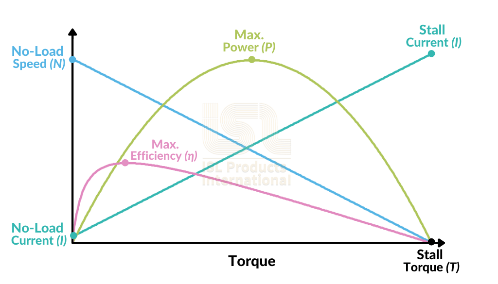
Normally a motor has torque/speed/power/efficiency curves like this:
(the missing Y axis label is speed, of course)
For most motors, like the diagram above, the max efficiency operating point is at about half the no-load speed for a given Vemf voltage.
The lead-acid battery will cap the voltage by itself at around 14.5V. It will pass current, and produce a little bit of hydrogen, which in a gel battery gets recombined back into acid. A car’s alternator normally produces around 14.2V which will continue to push a couple of amps into the battery even when it is fully charged.
If the current is too much then it will overheat or generate bubbles in the gel which can damage a small battery. If you really aggressively overcharge a lead acid battery with a lot of current then it will get hot enough to boil the electrolyte and explode - But this truck battery will have no problems at all being overcharged by your puny arms.