I also have this problem with odrive 3.4v with hoverboard.
Will try the caps.
Does this also happen with 3.5V?
Mine was 3.5 48v with hoverboard.
After googling around and checking different kind of hall sensor.
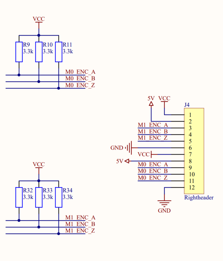
It seems that most of them you need around 10K pull resistor. In the schematics we do not have a pullup resistor for the ABZ encoder. I presume we are using the builtin pullup of the stm. Based on the datasheet these are typical 40K. Maybe this is the problem. The hall sink current is weak which also result in a weak signal that can get noise easy.
Anyone know where in the code I can disable the internal pull up so I can connect an external pull up on the encoder inputs.
Opes I missed that. Learn a lesson: Do not fix problems at 2:00 AM Thanks for the reply.
I just ran into this same problem. Axis1 would not work with my hub motors with the encoder throwing a 0x0010 error. I tried the suggested fix, soldering 22nF capacitors across the encoder inputs for M1 and it fixed the problem.
I then ran into a related problem where on one of my two Odrives axis0.encoder would throw a 0x0010 error the first time it dropped back to zero rpm. I tried the capacitor mod on the M0 encoder inputs and it seems to have also fixed that problem. So it appears hall encoder noise issues are not limited to the M1 inputs.
Might be worth mentioning this gothca on the hoverboard getting started page.
5 Likes
We fixed it by soldering some 47nF capacitors from the hall signals to GND to filter it out, as per this photo (after testing I’d say maybe around 22nF would be better)
I’m trying to replicate this on my newest oDrive. So I don’t make a mistake, can you help me recall what exact pins each capacitor is connected between, @madcowswe? Thank you!
1 Like
The connections are:
| Lead 1 | Lead 2 |
|---|---|
| Enc A | GND |
| Enc B | GND |
| Enc Z | GND |
I’m having the exact same issue but adding the capacitors doesn’t fix the problem (it fixed it on M1 but not M0). I’m using decently long leads to perhaps that is the cause. Would switching the shielded cables help?
Also the encoder.pos_estimate is reported correctly even when the error is thrown. Perhaps there is a way to solve it in software?
What value capacitors did you put, and where did you put them? Can we see a picture?
Yes, I’m going to post a picture when I get back to lab today.
They are 47nF capacitors. Currently added them using a breadboard (between ground and the ABZ pins)
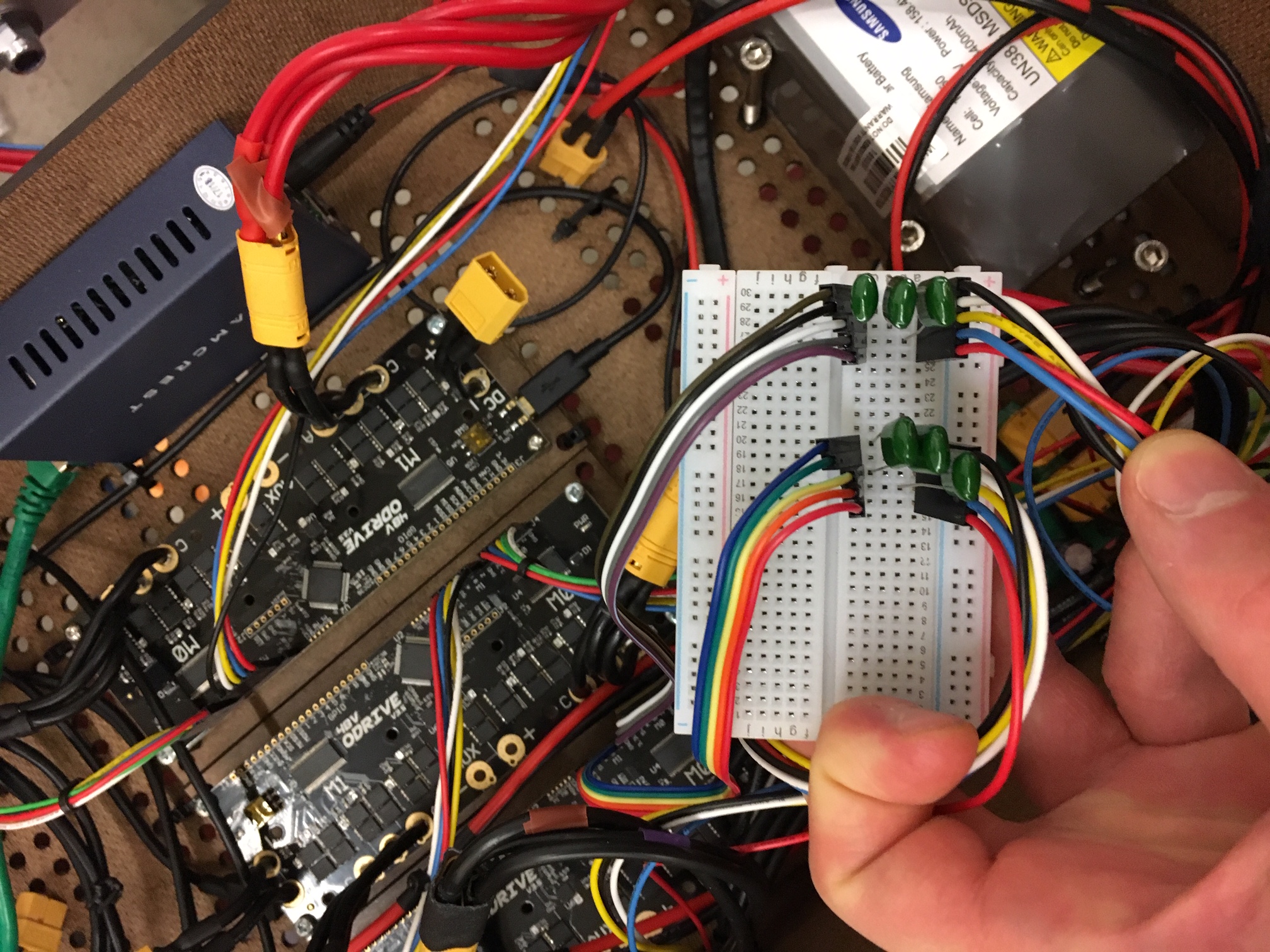
The capacitors have to be mounted very close to the ODrive, you can’t have it out on a breadboard.
1 Like
Hi,
I tried this out recently with some 47nF and also with 22nF as suggested, but it didn’t seem to fix the issue. I instead ignored the error, but I now get “ERROR_NO_RESPONSE” when I run a full calibration or encoder offset calibration. Not sure if that helps in terms of debugging, but I’d be happy to provide more info if needed.
Just got a couple of Q85 motors working after getting this error. 47nF were needed (at least on M1).
Tried 22nF on both motors, but kept getting the error so replaced the 22nF with 47nF on M1 and that solved the problem.
3 Likes
A nice solution that is less difficult to solder and still keeps the capacitors close to the ODrive board:
2 Likes
I like the protoboard solution. Any thoughts on also adding some additional resistors to create low pass filters? Would that improve things even more?
@wtip not necessarily. If the pass band of the filter is too low, then it will cause errors at high speeds, especially if using a high resolution encoder.
The filter should probably have a passband up to about 1MHz to avoid attenuating genuine encoder signals.
1 Like
I’m so glad the board is helpful! 
1 Like